cv-06 24 / 48
10秒後にBOOKのページに移動します
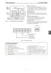
Azbil Corporation No. SS2-8114-0200 - 11 - Figure 8 Terminal connection Figure 7 Operating principle of block diagram - Input conversion block: Receives gate opening command signals of 1-5V DC under high impedance (4-20 mA DC signals are converted to voltage signals by a resistor of 250Ω connected to the input terminal) and converts to the level convenient for internal processing. - Mode switching block: Monitors gate opening command signals, judges signal “OFF”, and generates drive signals according to the preset mode. - Comparative operation block: Effects comparative operation between output axis rotating angle signals (potentiometer) and signals converted by the input conversion block. - Power drive block: Issues direct/reverse rotation command output to the motor depending on comparative judgment signals received from the comparative operation block. Ordering information When ordering, please specify; 1) 2) 3) 4) 5) 6) 7) 8) Model Number: HLS Nominal size × Cv required Type and rating of end connections Body and trim material, necessity of hardening Type of bonnet Valve and plug characteristics Type of actuator Valve action (direct or reverse), mode signal during input signal “OFF” 9) 10) 11) 12) 13) 14) 15) Accessories (limit switch.) Special requirement of oil-free treatment and etc. Name of flow medium Normal flow and maximum required flow Pressure of flow medium, upstream and downstream pressure at maximum and minimum, required flow Temperature and specific gravity of flow medium Viscosity of flow medium, inclusive or exclusive of slurry Regulator R/I Potentio. meter Input conversion (A/D) Mode switching Comparative operation Power drive Motor Valve opening output (4-20 mA DC) Input (4-20mA DC, 1 to 5V DC) Power supply (100V AC) Operating output + - + - IN 100V AC OUT External output signal (4-20 mA DC) Power supply (100V AC, 50/60 Hz) External input signal (4-20 mA /1-5V DC) 6 2