fi-01 171 / 226
10秒後にBOOKのページに移動します
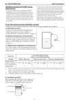
No. SS2-GTX00S-0100 Azbil Corporation - 6 - Handling precautions for HART specification devices . If you need to operate with a secondary host (HART communicator, etc.), set the communication interval of the primary host (DCS, device management system) to 8 seconds or more, or suspend communication from the primary host. If the primary host repeats HART communication within 8 seconds, the request from the secondary host may not be received (communication may not be possible). . If electrical noise in the environment prevents HARTcommunications with the host, take countermeasures such as separating the signal cables from the source of the noise, improving the grounding, changing to shielded signal cables, etc. Even if noise interferes with HART communications, the 4-20 mA analog signal will be unaffected and can be used for control. If this product is being operated in multidrop mode, there is a limit to the number of devices that can be used. If you are using multidrop mode, please consult with us. To use the remote seal type transmitter correctly A various accuracy regulation and notes of the remote seal type transmitter are as follows. .. : Shown for each item are the percentage ratio for .. (kPa), which is the greatest value of either the upper range value (URV)*1, the lower range value (LRV)*2 or the span. L : Flange length (mm) (In case, standard flange;L=0mm) .... : Temperature difference between upper flange and ambient temperature. A. Standard accuracy Linearity in constant ambient temperature and constant static pressure is shown. (Refer to “PERFORMANCE SPECIFICATIONS” on page 7) B. Ambient temperature characteristics Accuracy by the ambient temperature change in the main body under constant static pressure is shown. (Refer to “PERFORMANCE SPECIFICATIONS” on page 7) C. Wetted parts temperature characteristics Zero shift is shown, when the temperature fluctuate of process wetted parts of an upper flange and lower flange changes. Flange type 3 inches flush diaphragm flange 4 inches Extended diaphragm flange Fill fluid Regular / High temp. High-temp. and vacuum High-temp. and high-vacuum Wetted parts temperature characteristics (total shift of setting ranges) % % % C A B Liquid ..600.. 2L 50 .. + ------.. .. .. 1 55 ----- ..T 1000.. .. .. --------------- .. .. .. .. .. .. .. 900 2L 50 .. + ------.. .. .. 1 55 ----- ..T 1000.. .. .. --------------- .. .. .. .. .. .. .. 1200 3L 50 .. + ------.. .. .. 1 55 ----- ..T 1000.. .. .. --------------- .. .. .. .. .. .. .. D. Installation position When mounting the transmitter, leave a space of at least 10 cm under the upper nozzle of the tank. If the no space is available, please consult us. Upper liquid level Lower liquid level 10cm or more