fi-01 83 / 226
10秒後にBOOKのページに移動します
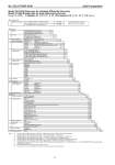
No. SS2-GTX00F-0100 Azbil Corporation - 12 - Model GTX35F(Flange type for standard differential pressure) Model GTX60F(Flange type for high differential pressure) Model No.:GTX_ _F-Selection I(I II III IV V VI VII)-Selection II(I II III IV V VI)-Option Note) *1 In case code J is selected, code C “Tantalum”, wetted part material of flange side should be selected. *2 Not applicable for the combination with code J “For chlorine service” of Fill Fluid. *3 Not applicable for the combination with code C “Tantalum” of Material of wetted part of flange side. *4 Not applicable for the combination with code F1, F6 “FM Explosion proof” of Explosion proof. *5 In case code M is selected, code X “No connection” of process installation of reference side should be selected. *6 Not applicable for the combination with code X "No connection" of Process installation of reference side. *7 Not applicable for the combination with code A2 "With external Zero/Span adjustment", Q1 "Safety Transmitter", and Q2 "NAMUR NE43 Compliant Output signal limits" of Option. *8 Not applicable for the combination with code E of Paint. *9 In case code X, H, or D is selected, the material of transmitter case is aluminum alloy. Basic Model No. Measuring span 2.5 to 100kPa (250 to 10,160mmH2O) GTX35F Flush flange type 2 inches 35 to 3500kPa (0.35 to 35kgf/cm2) GTX60F (50mm),1.5inches (40mm) Selection I I Output 4 to 20mA (SFN Communication) A 4 to 20mA (HART Communication) B Digital output (DE communication) *7 D II Fill fluid Regular type (Silicone oil) A For oxygen service (Fluorine oil) H For chlorine service (Fluorine oil) *1 J III Material (Meterbody cover, Vent/Drain plugs) Meterbody cover Vent / Drain plugs SCS14A 316 SST A IV Material (centerbody) Reference side Wetted part of flange side 316 SST 316 SST (Diaphragm: 316L SST) A 316 SST ASTM B575 (Equivalent to Hastelloy C-276) B 316 SST Tantalum *1 C 316 SST 316L SST D V Process connections of reference side Rc 1/2, with adapter flange *6 A Rc 1/4, with adapter flange *6 B Rc 1/4, without adapter flange *6 C 1/2 NPT internal thread, with adapter flange *6 D 1/4 NPT internal thread, with adapter flange *6 E 1/4 NPT internal thread, without adapter flange *6 F Open to atmosphere *5 H VI Process installation of reference side No connection *6 X Vertical piping, top connection A Vertical piping, bottom connection B VII Flange rating ANSI150 A1 ANSI300 A2 ANSI600 A3 JIS10K J1 JIS20K J3 JIS30K J4 JIS63K J6 JPI150 P1 JPI300 P2 JPI600 P3 VIII Flange size 1.5in./40A *2 *3 D 2in./50A E IX Flange type Flash type A X Flange material/bolt and nut material Flange Bolt and nut 304 SST 304 SST A 304 SST Carbon steel D 316 SST 304 SST E 316 SST Carbon steel H 316L SST 304 SST J 316L SST Carbon steel M X I Gasket face finish None Standard JISRa3.2(12.5S) A Selection II - I Electrical connection 1/2 NPT, Watertight A M20, Watertight *4 B II Explosion proof None XX FM Explosion proof F1 FM Intrinsically safe F2 FM Nonincendive F5 Combined of FM Explosionproof, Intrinsically safe and Nonincendive F6 ATEX Explosion proof A1 ATEX Intrinsically safe A2 ATEX Type n A5 IECEx Explosion proof, E1 IECEx Intrinsically safe E2 IECEx Type n E5 NEPSI Explosionproof *8 N1 NEPSI Intrinsically safe *8 N2 NEPSI Type n *8 N5 KOSHA Explosion proof *8 K1 III Built-in indicating smart meter None X With indicator A IV Paint *9 Standard X None (316 stainless steel housing) E Corrosion-proof (Urethane) H V Burnout feature UP Scale A DOWN scale B VI Mounting Bracket None X