fi-01 92 / 226
10秒後にBOOKのページに移動します
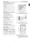
Azbil Corporation No. SS2-GTX00R-0100 - 3 - IECEx Flameproof and Dust Certifications Certificate No. IECEx KEM 08.0001 Ga/Gb Ex d IIC T6 Tprocess=85 °C -30 °C < Tamb < +75 °C IP66/67 Ga/Gb Ex d IIC T5 Tprocess=100 °C -30 °C < Tamb < +80 °C IP66/67 Ga/Gb Ex d IIC T4 Tprocess=110 °C -30 °C < Tamb < +80 °C IP66/67 Ex tD A21 IP66/67 T85 Tprocess=85 °C -30 °C < Tamb < +75 °C Ex tD A21 IP66/67 T100 Tprocess=100 °C -30 °C < Tamb < +75 °C Ex tD A21 IP66/67 T110 Tprocess=110 °C -30 °C < Tamb < +75 °C Caution - Use supply wires suitable for 5 °C above surrounding ambient IECEx Intrinsic safety and Dust Certifications IECEx KEM 07.0058X Zone 0 Ex ia IIC T4 TPROCESS = 105 °C -30 °C < Tamb < +60 °C IP66 / 67 ELECTRICAL PARAMETERS: Ui = 30 V, Ii = 93 mA, Pi = 1 W, Ci = 5 nF, Li = 0.5 mH Ex iaD 20 IP66 / 67 T105 TPROCESS = 105 °C -30 °C < Tamb < +60 °C IECEx Type n and Dust Certifications IECEx KEM 07.0058X Ex nL IIC T4 TPROCESS = 105 °C -30 °C < Tamb < +60 °C IP66 / 67 ELECTRICAL PARAMETERS: Ui = 30 V, Ci = 5 nF, Li = 0.5 mH Ex tD A21 IP66 / 67 T85 TPROCESS = 85 °C -30 °C < Tamb < +75 °C Ex tD A21 IP66 / 67 T100 TPROCESS = 100 °C -30 °C < Tamb < +80 °C Ex tD A21 IP66 / 67 T110 TPROCESS = 110 °C -30 °C < Tamb < +80 °C KOSHA Flameproof (Code K1) Ex d II C T6 Tprocess = 85 °C -30 °C < Tamb < +75 °C Ex d II C T5 Tprocess = 100 °C -30 °C < Tamb < +80 °C Ex d II C T4 Tprocess = 110 °C -30 °C < Tamb < +80 °C EMC Conformity 89/336/EEC, 92/31/EEC, 93/68/EEC Electromagnetic Compatibility (EMC) Directive Measuring span / Setting range / Working pressure range Figure 1 Working pressure and temperature of wetted parts section (for general purpose models) Figure 2 Working pressure and temperature wetted parts section (for oxygen and chlorine service) a. For high temperature b. For high temperature and vacuum, c. For high temperature and high vacuum Figure 3 Working pressure temperature of wetted parts section (For high temperature / high temperature and vacuum / high temperature and high vacuum) Measuring Span Setting Range Working Pressure Range GTX 35R 2.5 to100 kPa {250 to 10160 mmH2O} -100 to +100 kPa {-10160 to +10160 mmH2O} Up to flange rating (For negative pressures, see Figure 1, Figure 2 and Figure 3.) GTX 40R 35 to 700 kPa {0.35 to 7 kgf/ cm2} -100 to +700 kPa {-1 to +7 kgf/cm2} 133.3 101.3 80 53 27 13 8.0 5.3 2.0 {760} {15} 1.3 Working pressure P (kPa {mmHg} abs.) Temperature of wetted parts ( C) -50 -40 40 50 60 70 80 90 100 110 125 180 185 Operative limit Normal operating range Operative limit Unusable range 133 {1000} 101 {760} 53 {400} -40 -10 0 40 80 120 125 Working pressure P (kPa {mmhg} abs.) Temperature of wetted parts ( C) Normal operating conditions Operative limit conditions Operative limit conditions -40 0 40 100 200 300 -5 50 90 280 a b c 10 250 13 2 101.3 1.0 0.6 0.13 0.013 Temperature of wetted parts ( C) Working pressure (kPa abs.) 1 6