fi-04 105 / 228
10秒後にBOOKのページに移動します
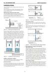
No. SS2-MGN200-0200 Azbil Corporation - 10 - Installation Notes The model NNK flowmeter installation requires attention on the following details. When designing the open channel, the mounting gate and the weir, it is required to design after good understanding of the flowmeter characteristics. .. Measuring method and water head The radical principle of this flow meter is an electromagnetic flow meter, and it is installed to the mounting gate board and submerged into the open channel to measure the flow rate. Flow rate formula (It is well-known as Bernoulli’s theorem) is as shown in below. Figure 10 Measurement principle drawing Moreover, when a large flow rate is measured, it is required to install a few dummy detectors having the same structure and the coefficient of discharge on the mounting gate board. Use the detector together with the dummy detectors while measuring the flowrate. In principle the flow rate of dummy detectors are of the same flow-rate with that of the detector. The converter which is in combination with detector will output a signal with integral multiples of the flow-rate based on the configured number of dummy detectors in the converter. Figure 11 Installation for dummy detector .. Water-submerged condition This flowmeter must always be used in submerged condition where the water fully fills the inside of the detector. [Bell mouth method] As for the bell mouth method, provide a weir on the downstream side, and its design should ensure submerged condition where the water fully fills the inside of the flowmeter with the open channel, the mounting gate and the weir. Figure 12 Water head design (Bell mouth type) [Elbow flange method] The Elbow flange method is a structure which ensures that the inside of the flow meter is fully filled with water without using the weir. Please note that the elbow flange must be installed only as an blow-up elbow open to the atmosphere. (Do not install as an blow-down elbow.) Figure 13 Water head design (Elbow flange method) .. Arrangement of detector and dummy [Bell mouth method] For large flow measurements using the bell mouth method, the number of dummy detectors can be increased in the vertical and the horizontal directions. When one or more dummy detectors are to be installed in the vertical and the horizontal directions, install at a location where it seems that the average flow velocity is generated and it avoids the wall side of the channel. The water head difference when a dummy detector is added in the vertical direction is different. It appears that flow velocity at the upper and lower position are different. It is confirmed that even the detector installed in the vertical direction will be able to get the flow rate within the rated accuracy due to the effect of the weir which is installed on the down stream side. [Elbow flange method] In case of the elbow flange method, the dummy detectors can be added only in the horizontal direction. Addition of the dummy detector in the vertical direction is not possible, as this method is different from the bell mouth method. In this method a weir is not installed and thus it is not possible to equalize the velocity of the water. Q: Flow rate A: Detector diameter k : Coefficient of discharge g : Gravitational acceleration h : Water head Q= k A 2gh HWL V h q Q q Q The detector is located on the upper right side. The others are the dummy detectors. The detector is located on the right side. The others are the dummy detectors. V H1 H2 H5 W=width of V open channel HWL Weir The upstream side straight line open channel=2W Distance to the downstream side weir=W V H3 H4 H5 HWL The upstream side straight-line open channel = 2W The blow-up exhaust of elbow should not be submerged.