fi-04 106 / 228
10秒後にBOOKのページに移動します
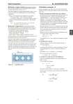
Azbil Corporation No. SS2-MGN200-0200 - 11 - .. Structure of open channel (recommended condition) The following conditions are recommendable for the design of the open channel (refer to Figure 12, 13) When these lengths for the open channel cannot be kept, it is necessary to provide a flow stabilizing plate to avoid generating wind drift etc. . Distance of the upstream side straight line open channel. . Use detector alone = Twice of detector diameter . Use detector with dummy = twice of open channel width W . Distance to the downstream side gate board = open channel width W Note) In case of the bell mouth type, a weir should be provided in the downstream side. .. Structure of gate board (recommended condition) The following conditions are recommendable for the design of the mounting gate board and flowmeter (detector and dummy). It is required to secure the following distance. . Distance from open channel wall = 150 mm . Distance from bottom = 100 mm . Detector pitch .. Refer to Figure 6 pitch between gate. The above data are to be followed for maintenance clearance and mounting the detector on to the gate board. Moreover, when using the Elbow flange method the accuracy is influenced when there is a water height difference, when the water outputs from the blow-up elbow into the atmosphere. Especially, when one or more dummy detectors are used, ensure to equalize and maintain the elbow blow-up water height (H4) difference by adjusting and aligning the direction of the blow out elbow movable section of the dummy detectors and the main detector. Figure 14 Installation pitch Calculation example - A Measure discharge water of flow rate 100 (m3/h) with the Bell mouth type detector in the open channel of width of the mounting gate (1 m). 1. Decide the length and width of the open channel Measurement in an open channel using the dummy detector in the bell mouth type for a width W, the calculation for the required length is, L = (2W on the upstream + detector F to F dimension + 1W on the down stream) therefore, L = 3W + Detector F to F dimension. The required depth of the open channel must be equivalent to height of the detector. The width of the open channel is to be designed considering the number of dummy detectors to be installed. Please refer Figure 6, to review an example for a detector with diameter 100 mm and whose detector casing width is 240 mm. The recommended gate installation pitch between detectors should be 245 mm or more. Moreover, when you secure both sides the maintenance space of 150 mm or more, refer Figure 14, then, 1000 - 150 × 2 = 700 700 ÷ 245 > 2 The installation of two or less (detector and dummy) becomes possible. 2. Calculate flow velocity. The flow velocity conversion table mentioned on page 2 is used and calculated. V = k × Q = k × q × n As mentioned in the table, for a detector diameter of 100 mm, the corresponding flow velocity conversion coefficient k is 0.03537 Measurable 2 nos. (1 no. detector + 1 no. dummy) Flow rate for each detector is 50 m3/h V = 0.03537 × 50 = 1.7685 (m/s) 3. Calculate the required water head difference. Water level calculation formula of water head difference of page 2 is used. k1 uses 0.053 by the constant. H1 = k1 × V2 = 0.053 × (1.7685)2 = 0.166 (m) Moreover, overflow depth H2 of the weir is calculated. Qt: flow rate, 1.84: constant, and W substitutes the width of the open channel. H2 = = = 0.061 (m) (100) (150) Gate installation pitch Qt 1.84 .. W .. 3600 ..---------------------------------------.. .. .. 2 .. 3 100 1.84 .. 1 .. 3600 ..-------------------------------------.. .. .. 2 .. 3 4 8