fi-04 10 / 228
10秒後にBOOKのページに移動します
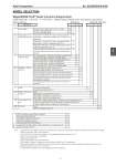
Azbil Corporation No. SS2-MGG410-0100 - 7 - MODEL SELECTION MagneW3000 PLUS+ Smart Converter (Integral style) Model MGG14C - I II III IV - V VI VII VIII - / Options (Some options can be selected per each model.) Basic model no. Selections Optional selections Note: 1. External DC power supply is necessary on analog 4-20 mA output. No analog output is expected without the external DC Power supply. 2. Must be selected for FM / CSA NI approval. 3. For FM/CSA N1, the Electrical connection / watertight gland selection code must be “4”. 4. Must be selected for Tag no. requirement. 5. Must specify Munsell No. 6. Must be specified for non-SI unit indication. 7. If no display is selected, configuration should be done by HART or SFC communicator. 8. When process fluid level in the flowtube is under electrodes, this function is activated and display and output are latched to zero. 9. Applicable detector size is from 15 to 80 mm. 10. Code H must be selected in case that NK approval model is regurred. MGG14C - I Power supply 100 to 120 V AC, 200 to 240 V AC, 47 to 63Hz M 24 V DC, noise filter 50 Hz P 24 V DC, noise filter 60 Hz R II Output signal / Communication (Note 10) Volume flow 4 to 20 mA DC output / with open collector pulse output / with HART communication or without communication H Volume flow 4 to 20 mA DC output / with open collector pulse output / with SFC communication (Note 1) B Volume flow DE output / with open collector pulse output / without communication (Note 1) C Fast Response model Volume flow 4 to 20 mA DC output / with open collector pulse output /without communication (Note 9) R III Electrical connection / Watertight gland G1/2 internal thread / with brass (Ni-plated) watertight gland 2 G1/2 internal thread / with plastic watertight gland 3 1/2NPT internal thread / without watertight gland (Note 2) 4 CM20 internal thread / without watertight gland 5 Pg13.5 internal thread / without watertight gland 6 G1/2 internal thread / with SUS304 watertight gland 7 IV Installation / Wiring direction Horizontal piping mounting / upstream side A Horizontal piping mounting / downstream side B Horizontal piping mounting / left side viewed from upstream C Horizontal piping mounting / right side viewed from upstream D Vertical piping mounting / downstream side (flow direction: downstream to upstream) E Vertical piping mounting / (flow direction: downstream to upstream) T V Finish Corrosion-resistant finish 1 Corrosion-proof finish (Note 7) 2 VI Display with data setting device None X Main display: instantaneous flow rate in % A Main display: instantaneous actual flow rate B Main display: indication of totalized value C VII Contact inputs / outputs 1 input and 1 output (ranging function, warning for contact input/output, etc.) 1 2 inputs (ranging function, external automatic zero adjustment input, etc.) 2 2 outputs (ranging function, warning for contact outputs.) 3 VIII Style code None X FM/CSA NI approval (Note 3) N Options Azbil Corporation version (Must be selected) Y Empty pipe detection function A Traceability certificate for converter C Plastic (Polycarbonate) window G Indication other than SI units (Note 6) H Attachment of the TAG number to the terminal box for converter (Note 4) J Specific color paint (Note 5) L 4 1