fi-04 111 / 228
10秒後にBOOKのページに移動します
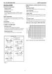
No. SS2-MGS200-0100 Azbil Corporation - 4 - INSTALLATION Electrical connection Integral model Connected to converter Remote model G1/2 (PF1/2) internal thread, 1/2 NPT internal thread, CM20 internal thread, Pg 13.5 internal thread Pipe connection ISO clamp (Size 15 to 125 mm (1/2 to 5 inches)) Tri-clamp (Size 15, 25, 40, 50, 80 mm (1/2, 1, 1., 2, 3 inches)) Grounding Resistance less than 100 Ω Length of straight pipe Upstream side A minimum five straight pipe diameters A minimum 10 straight pipe diameters is required if a diffuser/valve/pump is installed upstream side. Downstream side Two straight pipe diameters is recommended. Cable (between remote detector and converter) Maximum length 300 m (984 ft) (depending on fluid conductivity) Outer diameter 10 to 12 mm (0.4 to 0.47 inch) Signal cable Dedicated cable model MGA12W (O.D. 11.4 mm, 0.75 mm2 diameter) or equivalent (CVVS, CEEV, etc.) Excitation cable Dedicated cable model MGA12W (O.D. 10.5 mm, 2 mm2 diameter) or equivalent (CVV and others) Maximum cable length of MGA12W cable Figure 1 detector detector detector detector detector detector Right-angle joint Upstream side Greater than 5 dia. T joint Gate Value (completely open) Greater than 5 dia. Greater than 5 dia. Greater than 5 dia. Greater than 10 dia. Greater than 10 dia. Greater than 10 dia. Any Control Value Concentrator (considered as straight-pipe section) Any pump Diffuser with cone angle greater than 15 (If cone angle is 15 or less, considered as straight pipe) P Figure 2 Maximum cable length of MGA12W cable 300 2 5 10 20 200 50 100 1 3 5 10 20 50 100 200 500 1000 Process fluid conductivity [μ S/cm] Cable length [m]