fi-04 142 / 228
10秒後にBOOKのページに移動します
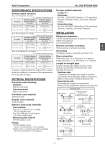
Azbil Corporation No. SS2-MTG300-0300 - 5 - PERFORMANCE SPECIFICATIONS Analog output accuracy Size: 2.5, 5 mm (0.1, 0.2 inch) Vs = velocity of setting range (m/s) Size: 10, 15 mm (3/8, 1/2 inch) Vs = velocity of setting range (m/s) Size: 25 to 200 mm (1 to 8 inches) Vs = velocity of setting range (m/s) Accuracy is guaranteed by the totalized flow volume under the condition of continuous flow measurement for 30 seconds or longer. PHYSICAL SPECIFICATIONS Converter case finishing Standard Baked acrylic paint Corrosion-proof Baked epoxy paint Converter case material Aluminum alloy Display cover material Tempered glass Detector main body materials Case material Size 2.5 to 15 mm (0.1 to 1/2 inch): SCS13 stainless steel Size 25 to 200 mm (1 to 8 inches): SUS304 stainless steel Measuring pipe material SUS304 stainless steel Flange SUS304 stainless steel (size 2.5 to 65 mm (0.1 to 2. inches)) Carbon steel + corrosion-preventive painting (size 80 to 200 mm (3 to 8 inches)) Process wetted materials Lining: PFA Electrodes SUS316L, ASTM B574 (Hastelloy C-276 equivalent), Titanium, Tantalum, Nickel, Zirconium, Platinum- Iridium Grounding rings SUS316, ASTM B575 (Hastelloy C-276 equivalent), Titanium, Tantalum, Zirconium, Platinum INSTALLATION Electrical connection 1/2NPT internal thread (must be selected for FM approval) CM20 internal thread G1/2 internal thread Remote converter mounting Wall mounting, 2-inch pipe mounting Grounding Grounding resistance should be less than 10 ... Pipe connection Wafer style (Size: 25 to 100 mm (1 to 4 inches)) Flange style (Size: 2.5 to 200 mm (0.1 to 8 inches)) Length of straight pipe Required straight pipe length clearance on the upstream side and the downstream side, while installing the detector. Upstream side A minimum 5D straight pipe length is required. A minimum 10D straight pipe length is required if a diffuser/valve/pump is installed upstream side. Downstream side 2D straight pipe length is recommended. (Where D is the nominal bore diameter of the detector) Vs (m/s) Velocity during measurement > Vs×50% Velocity during measurement < Vs×50% ±0.5% of rate ±0.5% of Vs ± % of rate ± % of Vs Vs (m/s) Velocity during measurement > Vs×40% Velocity during measurement < Vs×40% ±0.5% of rate ±0.5% of Vs ± % of rate ± % of Vs Vs (m/s) Velocity during measurement > Vs×30% Velocity during measurement < Vs×30% ±0.5% of rate ±0.5% of Vs ± % of rate ± % of Vs 1.0 .. Vs .. 10 0.3 .. Vs .. 1.0 0.5 Vs ------- 0.5 0.5 Vs ..-------.. + .. .. 1.0 .. Vs .. 10 0.3 .. Vs .. 1.0 0.5 Vs ------- 0.4 0.5 Vs ..-------.. + .. .. 1.0 .. Vs .. 10 0.3 .. Vs .. 1.0 0.5 Vs ------- 0.3 0.5 Vs ..-------.. + .. .. Figure 1 detector detector detector detector detector detector Right-angle joint Upstream side Greater than 5 dia. T joint Gate Value (completely open) Greater than 5 dia. Greater than 5 dia. Greater than 5 dia. Greater than 10 dia. Greater than 10 dia. Greater than 10 dia. Any Control Value Concentrator (considered as straight-pipe section) Any pump Diffuser with cone angle greater than 15 (If cone angle is 15 or less, considered as straight pipe) P 4 12