fi-04 170 / 228
10秒後にBOOKのページに移動します
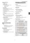
No. SS2-VRX100-0100 - 3 - Optional specifications Test Reports Calibration certificate Traceability certificate The following three documents are included. Traceability System Chart Traceability Certificate Test Report Material Certificate Material Certificate for process wetted materials. Strength Calculation Sheet A set of documents showing strength calculations for the housing, cap, and welded parts. Water Free Treatment Condensation is removed from process wetted materials surface. Oil Free Treatment Oil is removed from process wetted materials surface. Tagging Stamp the tag with the specified number and attached to the Vortexor. The maximum number of characters of the tag is 8. Valid characters are capital letters, whole numbers, and hyphens (-). Tropicalization Treatment Protect the Vortexor in harsh environment during transportation and/or storage. The following treatment is applied. Corrosion protection Moisture prevention Mildew proofing. PHYSICAL SPECIFICATIONS Finish Paint Converter case, cover Standard paint: corrosion-preventive acrylic resin Corrosion-resistant paint: baked acrylic resin Corrosion-proof paint: epoxy resin Main body material Non-Wetted Materials Meter Body non-wetted parts: SUS316, SCS14 Converter case: Aluminum alloy Bolts/nuts (optional): SUS304 Process-Wetted Materials Meter Body/Shedder Bar: SCS 16 (SUS 316L equivalent) Sensor Cap: SUS316L PERFORMANCE SPECIFICATIONS Flow Rate Range for Guaranteed Accuracy Re > 25,000 and flow velocity of 0.3 m/s or more Accuracy ±1% of rate (pulse output) ±1% of rate ±0.1% F.S. (4 - 20 mA DC output with dual sensor) Reproducibility ±0.2% of rate Process Fluid Temperature -20 to +160°C (waterproof model) -20 to +120°C (explosion-proof model) Process Fluid Pressure 5 MPa maximum Measurable Fluid Liquid Process Fluid Conditions Kinetic Viscosity: 20X10-6 m2/s or less No bubble is included. No significant pulsation flow or pulsating pressure exists. No slurry fluid and not adhesive fluid. Measurable Range Within the ranges specified in Table 1 and Table 2. Table 1. Accuracy Guaranteed Flow Range Minimum flow rate that assures accuracy of ..1% of rate (m3/h) Kinetic Diameter Viscosity (..10-6m2/s) 0.3 0.5 0.7 1 2 3 4 5 7 10 20 Maximum measurable flow rate (m3/h) 25 0.6 0.9 1.2 1.7 3.4 5.1 6.8 8.5 12 14 40 0.7 1.1 1.6 2.2 4.4 6.6 8.8 11 16 22 36 50 0.8 1.3 1.8 2.5 5.0 7.5 10 13 18 25 50 60 80 1.4 2.3 3.2 4.6 9.2 14 19 23 32 46 92 115 100 2.3 3.7 5.2 7.4 15 23 30 37 52 74 148 200 Table 2. Measurable Flow Rate Range (Note 2) Minimum measurable flow rate (m3/h) (Note 1) Diameter Kinetic Viscosity (..10-6m2/s) 0.3 0.5 0.7 1 2 3 4 5 7 10 20 Maximum measurable flow rate (m3/h) 25 0.1 0.15 0.2 0.28 0.6 0.9 1.2 1.4 2.0 2.8 5.7 14 40 0.2 0.3 0.4 0.53 1.0 1.5 2.0 2.5 3.5 5.0 10.0 36 50 0.3 0.4 0.52 0.74 1.4 2.0 2.7 3.4 4.7 6.7 14 60 80 0.5 0.8 1.0 1.4 2.4 3.6 4.8 6.0 8.4 12 24 115 100 1.0 1.5 1.8 2.4 3.9 5.8 7.7 9.6 14 20 39 200 Table 3. Flow Range with ±0.5% of rate accuracy (Note 4) Size Flow rate with ±0.5% of rate accuracy (m3/h) (mm) Process fluid: pure water/tap water 40 4.5 to 16 50 6.9 to 29 80 15 to 70 100 24 to 119 4 15