fi-04 172 / 228
10秒後にBOOKのページに移動します
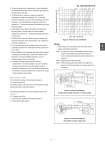
No. SS2-VRX100-0100 - 5 - 4. To ensure accurate flow measurement, ensure the gasket connecting the flowmeter and the connection pipe does not obtrude into the flow path. 5. If a pressure tap is required to ensure accurate flow measurement, install it at a distance of 2 - 7 times the flowmeterd diameter, away from the downstream end of the flowmeter. If a temperature tap is required, install it at a distance of 1 - 2 times the diameter, downstream away from the pressure tap. 6. When piping, ensure that the flowmeter and connection pipe are coaxial. Shift of center will cause unstable measurement and errors. Use the centering jig attached to the flowmeter. 7. Pulsation flow by such as a bellows pump or dosig pump may cause the error of the measurement. Use a damper to minimize pulsation flow. 8. For a line with valves, such as globe valves, that may be generating eccentric flow, install the flowmeter upstream of such valves. 9. When installing a heat exchanger that significantly changes the process fluid temperature, install it downstream of the flowmeter. If it must be installed upstream, secure a sufficient distance from the flowmeter. 10. Cavitation decreases the accuracy of the flow measurement. To prevent cavitation, be sure to maintain the lowest pressure in the line downstream (which is located at a distance of 2 to 7 times of the diameter of the flowmeter) at a pressure higher than or equal to the result of the expression shown below. Pd = 2.7 X ..P + 1.3 X P0 Pd: Downstream pressure (kPa, absolute pressure) ..P: Pressure loss (kPa) P0: Vapor pressure of process fluid at the temperature during measurement (kPa, absolute pressure) The following expression is used to calculate pressure loss: ..P = c X .. ..P: Pressure loss (kPa) c : Pressure loss coefficient (according to Figure 3) ..: Process fluid density (kg/m3) Figure 3. Pressure Loss Coefficient Wiring 1. Follow Figure 4 to wire cables for the flowmeter, power supply, and external equipment. Note 1. To make use of the communication function via the smart communicator, load resistance of 250 .. or more is required, including the cable resistance (see Figure 1). Note 2. Supply power for the flowmeter Note 3. When grounding the cable shield, use single point ground on the flowmeter side or the upper side of the equipment. Figure 4. Connection Diagram: Using Analog output and pulse or contact output Figure 5. Connection Diagram: Using Pulse or alarm output only 4 15