fi-04 181 / 228
10秒後にBOOKのページに移動します
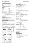
No. SS2-MVC200-0100 Azbil Corporation - 2 - Detector specifications Size: 50, 65, 80, 100, 150 mm Process connection: Flange JIS 10K Weight: 9 kg (50 mm), 11 kg (65 mm), 13 kg (80 mm), 18.5 kg (100 mm), 39.5 kg (150 mm) Material Wetted material: SUS316 Detector: SCS13 Detector cover: SCS13 Base: SUS304 Case: Aluminum alloy Cover: Polycarbonate Bolts and nuts materials: SUS304 Tube for remote type: Nylon (maximum 5 m)* Tube fitting: Brass + POM Note) *: One tube of 10 m is attached. Manufacturer: PISCO Co. Ltd. in Japan. Tube: NA0640-20R (the outside diameter: 6 mm, the inside diameter: 4 mm) Converter case fitting (only Aluminum case): Based acrylic paint Install position: Horizontal or vertical Mounting: Integral type or remote type Installation: Detector/Converter integral type, Wall mounting, 2-inch pipe mounting Straight pipe lengths: The minimum straight pipe length. Determine the length of a straight pipe section by referring to the following table. It is the minimum length of a straight pipe section required for the connection between this instrument and each joint of the upstream and downstream sides of the instrument. Each number in the table denotes a multiple of the pipe diameter Note) Valves in this figure are the gate value, ball valve but not globe value. Ambient temperature limit: -15 to 50°C Ambient humidity limit: 5 to 95% RH Electrical conduit: G1/2 (3 ports) Type of protection: IEC60529 IP54 Power supply: 90 to 250V AC Power consumption: 5 W (maximum) Grounding: The most effective grounding method is direct connection to earth ground with minimal impedance. Grounding resistance lower than 100 Ω. Output signal Analog output: 4 to 20 mA DC Pulse output: Open collector output Pulse width: 1 or 10 ms (Automatically selected according to the pulse weight.) Pulse frequency: 0.005 to 500 Hz Supply voltage: 10 to 30V DC Max current: 50 mA Display Main display: 8 digits Sub display: 16 digit, 2 lines Display contents:Simultaneously display % flow rate, flow rate, totalized flow, flow velocity, pressure, cost, totalized cost, various set up parameters Main/Sub display selection: Max. 2 contents are available in display contents Display unit: Volume flow: m3 Mass flow: kg, t Cost: , $ Velocity: m/s Pressure: MPa Time: d, h, min, s Measuring fluid: Compressed air, N2 and CO2 Fluid pressure 0.05 to 0.98 MPaG (Remote type: 0.05 to 0.9 MPaG) Fluid temperature limit: -15 to 70°C Temperature effect ±0.05%/°C of reading Performance Reference accuracy For the flow one tenth of maximum flow limit or more: ±3% of reading For the flow less than maximum flow limit of one tenth: ±(Qat1/10×3)/Q% of reading Qat1/10: 1/10 flow of maximum flow Q: measuring flow Upstream side L1 Downstream side L2 All the joints shown to the left One 90° bend Two or more 90° bends on a single plane 0.5 1.5 0.6 Two or more 90° bends not lying on a single plane Reducer 4.0 2.5 Expansion pipe Sluice valve(fully open) 1.5 2.5 Multivariable mass flow meter L1 L2 Multivariable mass flow meter L1 L2 Multivariable mass flow meter L1 L2 Multivariable mass flow meter L1 L2 3.5 D 3D f Multivariable mass flow meter L1 L2 D 0.75D f Multivariable mass flow meter L1 L2