fi-04 190 / 228
10秒後にBOOKのページに移動します
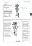
Azbil Corporation SS2-MVC300-0100 - 3 - STRUCTURE Figure 1 Configuration Figure 2 Structure Drain level Rising steam Rising drain (HP side) (LP side) Differential pressure generating part in the eTube The eTube has a differential pressure generating mechanism with a structure shown in Figure 2. Because the throttle has a streamlined shape, the flow separation, pressure losses and vortexes occurring in the throttle can be minimized. This means that the differential pressure generated by the differential pressure generating mechanism can be extracted with minimal losses and turned into differential pressure signals to be used for flow rate measurement. Therefore, eTube’s S/N ratio is very high, making it possible to extract stable differential pressure signals even if differential pressure is very low. In addition, the eTube produces a favorable side effect: a flow conditioning effect. This flow conditioning effect further produces the following advantages: . The length of straight pipes used in the upstream and downstream portions can be shortened considerably. . Flow meters can be installed to existing pipe lines without restrictions on locations in which to install them. Self water-sealed structure A diaphragm at the double-sided remote seal receives the differential pressure generated by the detecting part. This differential pressure is converted to flow rate signals output. If the diaphragm, which is made of stainless steel is heated to high temperature, the flowmeter may malfunction. To prevent this increase in the temperature of the diaphragm, the diaphragm is designed as a watersealed structure; the diaphragm is protected in water from overheating. This structure is called a self watersealed structure (SWS hereinafter). In a space enclosed by the diaphragm and the SWS cover flange, steam (fluid to be measured) is cooled, condenses and turns into water which cools the diaphragm to protect it from heat. Avoid applying heat to the SWS cover flange at the top of the detecting part. The SWS cover flange must be exposed to outside air to make it radiate heat. The approach to flow control and measurement so far described is basically identical to that for the conventional steam flow measurement mechanism using a differential pressure transmitter and an orifice. However, one difference should be noted with respect to the structure: in the case of the SWS structure, the seal pot used in the conventional instrumentation with a lead pipe is contained inside the differential pressure generating mechanism. Converter Measuring pressure and differential pressure simultaneously and separately with dual sensors Outputting mass flow rates based on density compensation calculations Output: Simultaneous analog and pulse outputs Display:Flow rates, pressure and temperature are output to be displayed on the LCD. Differential pressure generating part in the oval throat type Stable flow-rate output can be obtained thanks to the flow rectification effect. Low loss, minimum length of upstream and downstream straight pipes Size: 25mm to 150mm Rated pressure: JIS 10K, 20K, etc. Temperature: Up to 215..C Straight pipe lengths:0.5 D minimum Self water-sealed body cover 4 17