fi-04 203 / 228
10秒後にBOOKのページに移動します
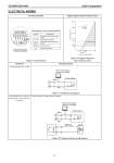
SS2-MVC300-0100 Azbil Corporation - 16 - ELECTRICAL WIRING Terminal connection Supply voltage and load resistance values Figure 9 Terminal block Figure 10 Supply voltage and load resistance values Connection Wiring connection If analog output only is used Figure 11 Analog wiring diagram If pulse output only is used or if pulse output is used with analog output Counter with an internal power supply: Figure 12 Analog and pulse wiring diagram Description of terminal symbols Symbol Description Terminals for power supply and output signals Terminals for resistance temperature sensors Pulse output terminals Shield terminal Terminal connection Grounding terminal (Terminal screw size: M4) 320 245 22.4 22.28 250 500 750 1000 1243 16.7 24 45 E: Power supply voltage (V) R: Load resistance (Ω) Operable range E-16.7 0.0229 R= Power supply Red Black Field communication software CommStaff Field communication software CommStaff Power supply Black Red Cunter Load