fi-04 31 / 228
10秒後にBOOKのページに移動します
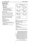
No. SS2-MGG200-0100 Azbil Corporation - 6 - INSTALLATION Electrical connection Integral model Connected to converter Remote model General model G1/2 (PF1/2) internal thread, CM20 internal thread, Pg 13.5 internal thread. FM/CSA Nonincendive model 1/2NPT internal thread for model MGG18 Watertight gland for model MGG19 Pipe connection Wafer (size 2.5 to 200 mm (0.1 to 8 inches)) Flange (size 2.5 to 1100 mm (0.1 to 44 inches)) Union (size 2.5 to 15 mm (0.1 to 1/2 inch)) Hose (size 2.5 to 15 mm (0.1 to 1/2 inch)) ISO Clamp (size 2.5 to 15 mm (0.1 to 1/2 inch)) Tri Clamp (size 2.5 to 15 mm (0.1 to 1/2 inch)) Nuts and bolts (for wafer models) S20C carbon steel, SUS304 stainless steel Grounding Resistance less than 100 Ω Length of straight pipe Upstream side A minimum five straight pipe diameters A minimum 10 straight pipe diameters is required if a diffuser/valve/pump is installed upstream side. Downstream side Two straight pipe diameters is recommended. Cable (between remote detector and converter) Maximum length 300 m (984 ft) (depends on fluid conductivity) Outer diameter 10 to 12 mm (0.4 to 0.47 inch) Signal cable Dedicated cable: MGA12W (O.D. 11.4 mm, 0.75 mm2) or equivalent (CVVS, CEEV etc.) Excitation cable Dedicated cable: MGA12W (O.D. 10.5 mm, 2 mm2) or equivalent (CVV and others) Maximum cable length of MGA12W cable Figure 1 Figure 2 Maximum cable length of MGA12W cable detector detector detector detector detector detector Right-angle joint Upstream side Greater than 5 dia. T joint Gate Value (completely open) Greater than 5 dia. Greater than 5 dia. Greater than 5 dia. Greater than 10 dia. Greater than 10 dia. Greater than 10 dia. Any Control Value Concentrator (considered as straight-pipe section) Any pump Diffuser with cone angle greater than 15 (If cone angle is 15 or less, considered as straight pipe) P 300 2 5 10 20 200 50 100 1 3 5 10 20 50 100 200 500 1000 Process fluid conductivity [μ S/cm] Cable length [m]