fi-04 61 / 228
10秒後にBOOKのページに移動します
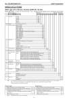
No. SS2-MGG200-0110 Azbil Corporation - 6 - MODELSELECTIONS Wafer type (15 to 100 mm ) Ceramic (Al203 99.7 %) liner Model MGG18D - I II III IV V VI VII VIII IX - X XI - Y/Options (some options can be selected per each model) Basic model no. Selections Optional selections Note: 1. This specification (without grounding ring) is applicable when the grounding is possible through pipe line. In case of plastic pipes or lined pipes, this selection is not applicable. Please select “M” as grounding ring selection code. 2. Must be selected for CSA/FM NI approval Remote type Integral type Note: 3. Must be selected for Tag no. requirement MGG18D - - I Line size 15 mm 015 25 mm 025 40 mm 040 50 mm 050 80 mm 080 100 mm 100 II Linear Ceramic (Al2O3 99.7 F%) C III Piping connection Wafer JIS 10K 11 Wafer JIS 20K 12 Wafer JIS 30K 13 Wafer ANSI 150 21 Wafer ANSI 300 22 Wafer JIS G3443-2 F12 (Size 80 mm or larger) 31 Wafer DIN PN10 41 Wafer DIN PN16 42 Wafer DIN PN25 43 Wafer DIN PN40 44 Wafer JPI 150 61 Wafer JPI 300 62 IV Electrode SUS316L L ASTM B574 (Hastelloy C-276 equivalent) C Titanium K Zirconium H Tantalum T Tungsten carbide W Platinum iridium for ceramic lining P V Grounding ring None (Note 1) X Platinum metallize M VI Electrical connection / watertight gland Integral type 1 Remote type G1/2 internal thread / without watertight gland 2 G1/2 internal thread / with brass (Ni-plated) watertight gland 3 G1/2 internal thread / with plastic watertight gland 4 1/2NPT internal thread / without watertight gland (Note 2) 5 CM20 internal thread / without watertight gland 6 Pg 13.5 internal thread / without watertight gland 7 G1/2 internal thread / with SUS304 watertight gland 8 VII Face-to-face dimensions Standard A VIII Installation / wiring direction Integral type H Remote type Upstream side (horizontal / vertical piping mounting) A Downstream side (horizontal / vertical piping mounting) B Horizontal piping mounting / left side viewed from upstream C Horizontal piping mounting / right side viewed from upstream D IX Calibration Standard A +/- 0.35 % of rate calibration (Size 40 to 100 mm (1 1/2 to 4 inches)) U Others .. X Finish Standard X Corrosion-resistant finish 1 Corrosion-proof finish 2 XI Bolt / nut None X Carbon steel 1 SUS304 2 Options Azbil Corporation version (must be selected) Y Options Azbil Corporation version (must be selected) Y Calibration certificate (sent to ordering location separately) A Calibration certificate (sent to ordering location separately) A Traceability certificate for detector B Traceability certificate for detector B Attachment of the TAG number plate to neck section for detector (Note 3) L Attachment of the TAG number plate to neck section for detector (Note 3) L Mirror-finish ceramic lining U Mirror-finish ceramic lining U