fi-04 8 / 228
10秒後にBOOKのページに移動します
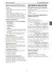
Azbil Corporation No. SS2-MGG410-0100 - 5 - Detectors coupled with MGG14C converter MGG14C works with the following Azbil Corporation's detectors. Integral style: MGG11/18D, MGG11/18F, MGG11/18U, MGS11/ 28U, KID90A Remote style: MGG11/18D, MGG11/18F, MGG11/18U, MGG12/19D, MGG12/19F, MGG12/19U, MGS11/ 28U, MGG15D, MGG15F, KID15B, KID20B, KID30B, KID90B, KID10B, KID11B, KID12B, NNK140, NNM (some types are not compatible.) Optional specifications Display (optional): LCD with backlighting Main display 7-segment, 6 digits Sub display 16 digits, two lines Display Flow rate in %, Actual flow rate, Totalized value Configuration parameters, Self-diagnostic, Write protect status Main display is selectable among “flow rate in %”, “actual flow rate” and “totalized value”. Data setting device Configuration by infrared ray touch sensor Infrared ray touch sensor: Four switches Write protect: Write protection level is set by switches in the converter. Write protect level is indicated on the display. Empty pipe detection When the detector is empty, the analog output, digital output and pulse output are fixed at zero. Display is latched to zero. Traceability certificate The following three documents are provided. . Traceability system chart . Traceability certificate . Calibration certificate Tag number on the terminal box The designated tag numbers (maximum 16 characters) should be stamped on a tag plate, which is attached to the terminal box. One line can contain 8 characters. Tag numbers exceed 8 characters will be stamped on the two lines. PERFORMANCE SPECIFICATION Measurable process fluid conductivity It depends on the cable length between the converter and the detector. With the detector size of 2.5 to 1100 mm (0.1 to 44 inch) 3 μS/cm or greater Accuracy (coupled with MGG, MGS and KID90 type detectors) Table 1 in combination with a detector