fi-07 19 / 26
10秒後にBOOKのページに移動します
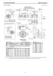
No. SS2-SLX100-0100 Azbil Corporation - 16 - T-S: Top - Side [Unit: mm] Note) 1: Dimensions shown inside the bracket is for pressure rating of JIS 20K, JIS 30K, JPI 300 and ANSI 300. 2: When pressure rating is JIS 10K, hub shown in the figure above will not be provided. (Standard, with indicator) (Standard, without indicator) (for high temperature, with indicator) (for high temperature, without indicator) (Standard) (for high temperature) Housing Sensor housing Torque tube Extension Bonnet Bolt / nut (refer to table 2) Gasket Bolt / nut (refer to table 2) pc. Gasket Chamber size: 3 in. Float Terminal connection (Terminal screw size: M4) refer to table 1 M4 Terminal screw for grounding Electric conduit connection port Mounting position: right side Note 1 drain plug Case Table 1. Terminal Table 2. Bolt / nut material Table 4. Size H Symbol Description S+, S- Power suuply and output signal CHK+, CHK- Terminal for check meter M+, M- Terminal for ammeter installed outside E Ground terminal Bolt / nut material U, M, A, E SNB7 / S45C * D, W SUS304/SUS304 Measuring range (mm) H 0 to 30 0 300 0 to 35 0 350 0 to 40 0 400 0 to 50 0 500 0 to 60 0 600 0 to 70 0 700 0 to 80 0 800 0 to 100 0 1000 0 to 120 0 1200 0 to 150 0 1500 0 to 200 0 2000 Table 3. Connecting flange size * When Y131 is specified, bolt/nut material shall be SUS304/SUS304. 40 mm 50 mm 1 1/2 in. 2 in. 40 mm 50 mm 40 mm 50 mm 1 1/2 in. 2 in. D 140 155 127 152 140 155 160 165 155 165 G 81 96 73.2 91.9 81 96 90 105 73.2 91.9 T 16 16 18 19.5 18 18 22 22 21 22.5 f22 1.6 1.6 2222 1.6 1.6 C 105 120 98.6 120.6 105 120 120 130 114.3 127 H-N 19-4 19-4 16-4 19-4 19-4 19-8 23-4 19-8 22-4 19-8 Flange rating JIS 10 K RF JIS 20 K RF JIS 30 K RF JPI ANSI 150 RF JPI ANSI 300 RF Note 2 ) (Optional) (with indicator) (without indicator) External adjustment switch (when with indicator)