cv-07 30 / 138
10秒後にBOOKのページに移動します
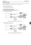
Azbil Corporation No. SS2-AVP772-0100 System Configuration The wire connection method for this equipment differs depending on the input and output signals, so please reference the following system configurations. .................................................. the following three working examples as examples of instrumentation. 1) PST device with solenoid valve: Case 1 2) ESD .............. device with PST function: Case 2 3) Smart Valve Positioner with ESD function: Case 3 1) Case 1 (PST devi..e with solenoid valve) 1-1) System Configuration without Output Signals (Model AVP 7..2) 1-1-1) Analog current (4-20 mA) signal input ....stem configuration ...... Model AVP 772. AO DO Solenoid Valve HART Host Emergency ....ut ..own Valve 0/24 V DC (Emergency ..hut ..own Signal) 4-20 mA DC Power Supply IN IN Logic Solver Figure 2. System Configuration ...... Model AVP 772 with Solenoid Valve 1-1-2) ................ voltage signal (0/24 V DC) inputs ..ystem configuration ...... Model AVP 792. Solenoid Valve Emergency Shut ..own Valve Logic Solver DO DO 0/24 V DC (Emergency Shut ..own Signal) IN IN Resistance: 500 Ω 0/24 V DC Power Supply HART Host Figure 3. System Configuration ...... Model AVP 792 with Solenoid Valve 5 7 3