cv-07 34 / 138
10秒後にBOOKのページに移動します
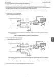
Azbil Corporation No. SS2-AVP772-0100 2-2) System Configuration with Analog Output (Model AVP 7..1) Model AVP 7..1 .................................................................. the valve's position. This signal .......................... burnout if abnormalities are detected with the self diagnosis (during serious failures) or PST. To output the position signal to the host monitoring device using analog values, configure a system that supports analog signals. The output of position of 0% will be 4 mA, and output of position of 100% will be 20 mA. With this system configuration, the analog signal from the instrument is directly output to the host monitoring system. 2-2-1) Analog current (4-20 mA) signal input ....stem configuration ...... Model AVP 771. Emergency Shut ..own Valve AO AI Analog Signal 4-20 mA DC (Opening signal or self diagnosis (................ / PST abnormality) 4-20 mA 250 Ω Resistance *1 24 V DC Power Supply *1 Logic Solver HART Host (Emergency ..hut ....own ..ignal / power supply) Note: the external load resistance will be the sum of the host logic solver's input resistance and.......................................... ........................ .............. Figure 10. System Configuration ...... Model AVP 771 Used as ESD Device 2-2-2) ................ voltage signal (0/24 V DC) inputs ....stem configuration ...... Model AVP 791. Emergency Shut ..own Valve DO AI Analog Signal 4-20 mA DC (Opening signal or self diagnosis (failure) / PST abnormality) 250 Ω Resistance *1 24 V DC Power Supply *1 0/24 V DC (Emergency ..hut ..own ..ignal / power supply) Resistance *1: 500 Ω HART Host Logic Solver Note: the external load resistance will be the sum of the host logic solver's input resistance and ........................................ .................................... Figure 11. System Configuration for Model AVP 791 Used as ESD Device *1: please reference Figure 1 for details regarding the power supply and resistance. 9 7 3