cv-07 50 / 138
10秒後にBOOKのページに移動します
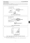
Azbil Corporation No. SS2-AVP300-0100 - 5 - Typical installation Figure 1 shows wiring for the model AVP300/302. In this case, you can connect a AVP to its terminal for communications. Figure 2 shows wiring for the model AVP301 (Smart positioner with travel transmission). In this case, you can connect a AVP anywhere along the travel transmission wiring for communications. Note) *1: For load resistance, refer to Figure 3. Note) Supply voltage shall be limited to 45 V DC *2. Load resistance = Resistance for Monitoring system + 250Ω*1 + Resistance of supply voltage*1 Figure 1 Wiring for model AVP300/302 HART Communicator (Model AVP302 only) 300 Series Host Controller CommStaff (Model CFS100) IIN IIN IOUT IOUT Figure 2 Wiring for model AVP301 Figure 3 Supply voltage for travel transmission vs. load resistance characteristic 0 1 2 3 4 x10²kPo 0 1 2 3 4 x10²kPo COVER MUST BEKEPT TIGHT WHILE CIRCUITS ARE ALIVE Controller 4 - 20mA DC 4 - 20mA DC I IN I IN I OUT I OUT Monitoring System 250W 24V DC*1 *1 Field Communication Software CommStaff Model CFS100 605 245 1560 16.5 24 45 Supply Voltage (V DC) Load Resistance (Ω) *2 Operable range 7 4