cv-07 61 / 138
10秒後にBOOKのページに移動します
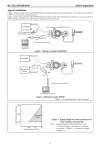
No. SS2-AVP200-0100 Azbil Corporation - 4 - Typical installation Figure 1 shows wiring for the model AVP200 (Smart positioner without travel transmission). In this case, you can connect a SVP to its terminal for communications. Figure 2 shows wiring for the model AVP201 (Smart positioner with travel transmission). In this case, you can connect a SVP anywhere along the travel transmission wiring for communications. Figure 1 Wiring for model AVP200/202 Figure 2 Wiring for model AVP201 Note) *1: For load resistance, refer to Figure 3. Figure 3 Supply voltage for travel transmission vs. load resistance characteristic Note) Supply voltage shall be limited to 45 V DC *2. Load resistance = Resistance for Monitoring system + 250・リ(.1) + Resistance of supply voltage (*1). Controller 4.20mA DC I IN I IN I OUT I OUT CommStaff Model CFS100 SFN communication interface HART communicator (Model AVP302 only) Red Black HART Communicator (Model AVP302 only) Controller 4.20mA DC 4.20mA DC I IN I IN I OUT I OUT Monitoring System 250W 24V DC *1 CommStaff Model CFS100 SFN communication interface Black Red 605 245 1560 16.5 24 45 Operable Range Supply voltage (V DC) Load Resistance (Ohms) *2