cv-07 72 / 138
10秒後にBOOKのページに移動します
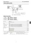
Azbil Corporation No. SS2-AVP100-0100 - 3 - TYPICAL INSTALLATION Figure 1 shows wiring for model AVP100/102 (Smart positioner). In this case, you can communicate with SVP at its terminal. MODEL SELECTION Analog Signal (4 to 20mA.DC.) Analog Signal (4 to 20mA.DC.) with HART communication protocol Configuration Following shows default and optional settings of each configurable parameter of SVP Useless otherwise specified, the Smart Valve Positioner will be shipped with the following configuration 1. Input control signal 4 to 20 mA The minimal span for custom range = 4 mA 2. Output characteristic Linear EQ or QO can be ordered or set by user. 3. Valve action Direct (Plug above seat) Reverse (Plug below seat) can be ordered or set by user. Figure 1 Wiring for model AVP100/102 Model Selections Options AVP100 - (1) - (2) (3) - (4) (5) AVP102 - (1) - (2) (3) - (4) (5) Code (1) Structure Water-proof P NEPSI Intrinsically safe H (2) (3) None XX Supply Air-pressure 140 < Ps < 150 kPa with T-joint and pressure gauge (200 kPa) 1X Classification 150 < Ps < 300 kPa with T-joint and pressure gauge (400 kPa) 2X Pressure gauge 300 < Ps < 450 kPa with T-joint and pressure gauge (600 kPa) 3X T-joint 450 < Ps < 700 kPa with T-joint and pressure gauge (1000 kPa) 4X (4) (5) Option None XX With bracket for PSA1, 2 DS With bracket for PSA3, 4 DQ With bracket for HA2, 3 DT With bracket for HA4 DN Controller 4 to 20mA DC + + + - - - I IN I IN CommPad CommStaff Model CFS100 HART Communication CommStaff Model CFS100 HART Communication for model AVP102 7 6