fi-01 132 / 226
10秒後にBOOKのページに移動します
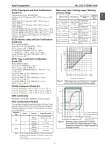
Azbil Corporation No. SS2-GTX00U-0100 - 3 - IECEx Flameproof and Dust Certifications (Code E1) Certificate No. IECEx KEM 08.0001 Ga/Gb Ex d IIC T6 Tprocess=85°C -30°C < Tamb < +75°C IP66/67 Ga/Gb Ex d IIC T5 Tprocess=100°C -30°C < Tamb < +80°C IP66/67 Ga/Gb Ex d IIC T4 Tprocess=110°C -30°C < Tamb < +80°C IP66/67 Ex tD A21 IP66/67 T85 Tprocess=85°C -30°C < Tamb < +75°C Ex tD A21 IP66/67 T100 Tprocess=100°C -30°C < Tamb < +75°C Ex tD A21 IP66/67 T110 Tprocess=110°C -30°C < Tamb < +75°C Caution - Use supply wires suitable for 5°C above surrounding ambient IECEx Intrinsic safety and Dust Certifications (Code E2) IECEx KEM 07.0058X Zone 0 Ex ia IIC T4 TPROCESS = 105 °C -30 °C < Tamb < +60 °C IP66 / 67 ELECTRICAL PARAMETERS: Ui = 30 V, Ii = 93 mA, Pi = 1 W, Ci = 5 nF, Li = 0.5 mH Ex iaD 20 IP66 / 67 T105 TPROCESS = 105 °C -30 °C < Tamb < +60 °C IECEx Type n and Dust Certifications (Code E5) IECEx KEM 07.0058X Ex nL IIC T4 TPROCESS = 105 °C -30 °C < Tamb < +60 °C IP66 / 67 ELECTRICAL PARAMETERS: Ui = 30 V, Ci = 5 nF, Li = 0.5 mH Ex tD A21 IP66 / 67 T85 TPROCESS = 85 °C -30 °C < Tamb < +75 °C Ex tD A21 IP66 / 67 T100 TPROCESS = 100 °C -30 °C < Tamb < +80 °C Ex tD A21 IP66 / 67 T110 TPROCESS = 110 °C -30 °C < Tamb < +80 °C KOSHA Flameproof (Code K1) Ex d II C T6 Tprocess = 85 °C -30 °C < Tamb < +75 °C Ex d II C T5 Tprocess = 100 °C -30 °C < Tamb < +80 °C Ex d II C T4 Tprocess = 110 °C -30 °C < Tamb < +80 °C EMC Conformity 89/336/EEC, 92/31/EEC, 93/68/EEC Electromagnetic PED Conformity (97/23EC) The maximum pressures applicable under the Sound Engineering Practice (SEP) section of the Pressure Equipment Directive depend on the type of fluid measured, as shown in the table below. Note) Group 1 comprises fluids defines as: explosive, extremely flammable, highly flammable, flammable, very toxic, toxic and oxidizing. Group 2 comprises all other fluids not refer to group 1 Measuring span / Setting range / Working pressure range Measured fluid Group * Pressure Applicable models Gas 1 200 bar (20 MPa) All models except GTX32D, 42D, 72D, 82G 2 1,000 bar (100 MPa) All models Liquid 1 500 bar (50 MPa) All models 2 1,000 bar (100 MPa) All models Measuring Span Setting Range Working Pressure Range Overload Resistant Value GTX 35U 2.5 to 100 kPa {250 to 10160 mmH2O} -100 to 100 kPa {-10160 to 10160 mmH2O} Up to flange rating (For negative pressures, see Figures 1, 2 and 3.) None GTX 60U 35 to 3500 kPa {0.35 to 35kgf/ cm2} -100 to 3500 kPa {-1 to 35 kgf/cm2} Up to flange rating (For negative pressures, see Figures 1, 2 and 3.) 5250 kPa {52.5 kgf/ cm2} GTX 71U 0.7 to 10 MPa {7 to 102 kgf/cm2} -0.1 to 10 MPa {-1 to 102 kgf/ cm2} Up to flange rating (For negative pressures, see Figures 1, 2 and 3.) 15.3 MPa {153 kgf/ cm2} GTX 82U 0.7 to 42 MPa {7 to 420 kgf/cm2} -0.1 to 42 MPa {-1 to 420 kgf/ cm2} Up to flange rating (For negative pressures, see Figures 1, 2 and 3.) 63MPa {630 kgf/ cm2} Figure 1 Working pressure and temperature of wetted parts section (for general purpose models) a. For high temperature b. For high temperature and vacuum, c. For high temperature and high vacuum Figure 2 Working pressure temperature of wetted parts section (For high temperature / high temperature and vacuum / high temperature and high vacuum) 133.3 101.3 80 53 27 13 8.0 5.3 2.0 {760} {15} 1.3 Working pressure P (kPa {mmHg} abs.) Temperature of wetted parts ( C) -50 -40 40 50 60 70 80 90 100 110 125 180 185 Operative limit Normal operating range Operative limit Unusable range -40 0 40 100 200 300 -5 50 90 280 a b c 10 250 13 2 101.3 1.0 0.6 0.13 0.013 Temperature of wetted parts ( C) Working pressure (kPa abs.) 1 7