fi-01 133 / 226
10秒後にBOOKのページに移動します
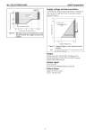
No. SS2-GTX00U-0100 Azbil Corporation - 4 - Supply voltage and load resistance 17.9 to 42V DC. Reverse polarity protection is standard. A load resistance of 250 Ω or more is necessary between loops.See Figure 4. Output Analog output (4 to 20 mA DC) with DE protocol Analog output (4 to 20 mA DC) with HART protocol Digital output (DE protocol) Output signal 3.6 to 21.6 mA 3.8 to 20.5 mA (NAMUR NE43 compliant) Failure Alarm Upper: 21.6 mA or more Lower: 3.6 mA or less Figure 3 Working pressure and temperature of wetted parts section (for oxygen and chlorine models) 133.3 {1000} 101 {760} 53 {400} -40 -10 0 40 80 120 125 Working pressure P (kPa {mmHg} abs.) Temperature of wetted parts ( C) Normal operating conditions Operative limit conditions Operative limit conditions Figure 4 Supply voltage vs. load resistance characteristics Note) For communication with SFC, a load resistance of 250 Ω or more is necessary. 1345 1482 Load resistance (W) Supply voltage - 12.5 0.0219 245 0 17.9 42 45 Load resistance (Ω) Supply voltage (V DC) Operating Range = Operative limit 12.5