fi-01 188 / 226
10秒後にBOOKのページに移動します
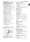
Azbil Corporation No. SS2-PTG300-0100 - 3 - COMMON SPECIFICATIONS Type of protection JIS C0920 watertight, NEMA 3 and 4X, IEC IP67 FM Explosionproof approval Explosionproof for Class I, Division 1, Groups A, B, C and D, T4, ambient temperature = 60°C Dust-ignition for Class II and III, Division 1, Groups E, F and G, T6 ambient temperature = 60°C, Type 4X FM Intrinsically safe approval Intrinsically safe for Class I, II, III, Division1, Group A, B, C, D, E, F, G T4 / Class I, Zone 0, AEx ia IIC T4 KOSHA Flameproof approval Ex d IIC T4 NEPSI Flameproof approval Ex d IIC T4 Ambient temperature: -25°C to +60°C Temperature of wetted part: -25°C to +130°C Ex d IIC T5 Ambient temperature: -25°C to +60°C Temperature of wetted part: -40°C to +95°C Ex d IIC T6 Ambient temperature: -25°C to +40°C Temperature of wetted part: -40°C to +80°C NEPSI Dust ignition-proof DIP DP T11 ATEX Flameproof approval ..0344 II 2 G EEx d IIC T4 MAX. AMBIENT TEMP.: +60°C PTB 02 ATEX 1117 IP67 Supply voltage and load resistance Refer to Figure 1. Power supply and voltage effect 0.005% F.S./V Output / Communication Model PTG71 . Analog output (4 to 20 mA DC) with SFN communication Model PTG72 . Analog output (4 to 20 mA DC) with HART protocol . DE output with CommStaff communication Response speed Approx. 400 ms Vibration Tolerance Less than 100 Hz : 2 G 100 to 2000 Hz : 1 G Zero adjustment Internal zero adjustment function CE conformity . EN50081-2-1993, Electromagnetic Compatibility- Generic Emission Standard, Part 2: Industrial Environment . EN50082-2-1995, Electromagnetic Compatibility- Generic Immunity Standard, Part 2: Industrial Environment . EN61010-1-1993, Safety requirements for electrical equipment, control and laboratory use, Part: General requirement Finish Baked acrylic paint, metallic green (Munsell 5G7/8) Electrical connection 1/2 NPT internal thread Mounting . Direct mounting on a pipe (line mount) . 2-inch pipe mounting . Wall mounting When mounting a PTG transmitter, consider its characteristics against vibration and overall vibration including piping. Use an optional mounting bracket when mounting it onto 2-inch pipe or wall. Optional specifications Built-in indicating meter The digital LCD indicator (optional) displays engineering units and can be set freely between -19999 and 19999 (4.5 digits). Corrosion-proof finish Corrosion-proof paint (Baked epoxy paint), fungusproof finish Remote communication function Remote configuration function by using the smart communicator. Oil free finish Oil is removed from the wetted parts before shipment. Figure 1 Supply voltage vs. load resistance characteristics R= E-11.5 0.0218 With and without remote communication Without remote communication A minimum of 250W of loop resistance is required for communication with the HART communication. R E 850 250 0 11.5 16.9 30 External load resistance (W) Supply voltage (V DC) 1 10