fi-06 39 / 46
10秒後にBOOKのページに移動します
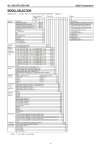
No. SS2-KFL100-0100 Azbil Corporation - 6 - MODEL SELECTION Model KFL__ - I II III - IV V VI VII VIII IX X XI XII XIII XIV - Options *9 Basic model no. *7 Selections Options Note) *1~10: refer to next page. KFL - - Model Torque tube KFL X No options Function Indicating transmitter B 0 M Internal manual loader (with A/M switch) Indicating controller (local type) B 1 K With external manual SP setting knob Indicating transmitter and controller (local type) B 2 4 Water and oil free treatment (only the Indicating controller (cascade type) B 3 SUS material) Range 1000 mm or less Indicating transmitter and controller (cascade type) B 4 5 Oil free treatment (only the SUS materiNo selection 0 als) Range 1000 mm or less P + Manual reset 1 6 Test report *10 PI 2 7 Five point check *10 PID 3 8 Mil sheet PD + Manual reset 4 9 With air set PI + Batch 5 B Dye check On-Off 6 C Without float *5 Differential gap 7 D Without chamber *6 P + External reset 8 PD + External reset 9 Specific gravity For medium specific gravity 6 1 For low specific gravity *1 6 2 Range of standard measuring setting range (mm) 0 - 300 (0.2 < low sp.gr. < 0.6, 0.6 < medium sp.gr. < 1.6) 0 3 0 - 350 (0.2 < low sp.gr. < 0.6, 0.6 < medium sp.gr. < 1.6) A 3 0 - 400 (0.2 < low sp.gr. < 0.6, 0.6 < medium sp.gr. < 1.6) 0 4 0 - 450 (0.2 < low sp.gr. < 0.6, 0.6 < medium sp.gr. < 1.6) A 4 0 - 500 (0.15 < low sp.gr. < 0.4, 0.4 < medium sp.gr. < 1.6) 0 5 0 - 600 (0.15 < low sp.gr. < 0.4, 0.4 < medium sp.gr. < 1.6) 0 6 0 - 700 (0.1 < low sp.gr. < 0.4, 0.4 < medium sp.gr. < 1.6) 0 7 0 - 800 (0.1 < low sp.gr. < 0.4, 0.4 < medium sp.gr. < 1.6) 0 8 0 - 1000 (0.1 < low sp.gr. < 0.4, 0.4 < medium sp.gr. < 1.6) 1 0 0 - 1200 (0.1 < low sp.gr. < 0.4, 0.4 < medium sp.gr. < 1.6) 1 2 0 - 1500 (0.1 < low sp.gr. <0.4, 0.4 < medium sp.gr. < 1.6) 1 5 0 - 2000 (0.1 < low sp.gr. < 0.4, 0.4 < medium sp.gr. < 1.6) 2 0 Other X X Process connection External chamber type, side-side flanged (S-S) 1 External chamber type, side-bottom flanged (S-B) 2 External chamber type, top-bottom flanged (T-B) 3 External chamber type, top-side flanged (T-S) 4 Internal float type, top flanged (T) L1 dimensions must be specified. 5 Other X Element materials Bonnet / Chamber (B & C) Torque tube housing (TH) Carbon steel Carbon steel 1 SUS304 SCS13A 2 SUS316 SCS14A 3 SUS316L SCS16A 4 Other X Other materials *3 (Temperature range *2) Torque tube: Inconel (350 to 400°C) (with radiation fin) U Torque tube: Inconel (200 to 350°C) (with radiation fin) M Torque tube: Inconel (0 to 200°C) A Torque tube: SUS316L (0 to 200°C) E Torque tube: SUS316L (-196 to 0°C) *2 D Other X Working pressure range *8 JIS 10K 1 JIS 20K 2 JIS 30K 3 JIS 63K 4 ANSI 150 (RF smoothness) A ANSI 150 (RF serration) B ANSI 300 (RF smoothness) C ANSI 300 (RF serration) D ANSI 600 (RF smoothness) E ANSI 600 (RTJ) F JPI 150 G JPI 300 H JPI 600 J JPI 600 (RTJ) K Other *4 X Flange size 1. inch (40 mm) (Applicable to external chamber type) 1 2 inches (50 mm) (Applicable to external chamber type) 2 3 inches (80 mm) (Applicable to internal chamber type) (only medium specific gravity) 3 4 inches (100 mm) (Applicable to internal chamber type) 4 5 inches (125 mm) (Applicable to internal chamber type) (only low specific gravity) *1 5 Other X Air piping connections Rc1/4 (PT1/4 internal thread) (Nameplate: Japanese) A 1/4NPT internal thread (Nameplate: English) B Unit / Pneumatic signal kgf/cm2/ 0.2-1 kgf/cm2 1 PSI/ 3-15 PSI 2 bar/ 0.2-1.0 bar 3 Pa/ 20-100 kPa 4 Pa/ 19.6-98.1 kPa 8