fi-07 17 / 26
10秒後にBOOKのページに移動します
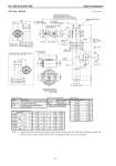
No. SS2-SLX100-0100 Azbil Corporation - 14 - S-B: Side - Bottom [Unit: mm] Note) 1: Dimensions shown inside the bracket is for pressure rating of JIS 20K, JIS 30K, JPI 300 and ANSI 300. 2: When pressure rating is JIS 10K, hub shown in the figure above will not be provided. Note 1 (Standard, with indicator) (Standard, without indicator) (for high temperature, with indicator) (for high temperature, without indicator) (Standard) (for high temperature) Housing Sensor housing Torque tube housing Extension Bonnet Bolt / nut (refer to table 2) Gasket Bolt / nut (refer to table 2) pc. Gasket Chamber size: 3 in. Float Note 2 Terminal connection (Terminal screw size: M4) refer to table 1 M4, Terminal screw for grounding Electric conduit connection port Mounting position: right side Table 1. Terminal Table 2. Bolt / nut material Table 4. Size H Symbol Description S+, S- Power supply and output signal terminal CHK+, CHK- Terminal for check meter M+, M- Terminal for ammeter installed outside E Ground terminal Bolt / nut material U, M, A, E SNB7 / S45C * D, W SUS304/SUS304 Measuring range (mm) H 0 to 30 0 300 0 to 35 0 350 0 to 40 0 400 0 to 50 0 500 0 to 60 0 600 0 to 70 0 700 0 to 80 0 800 0 to 100 0 1000 0 to 120 0 1200 0 to 150 0 1500 0 to 200 0 2000 Table 3. Connecting flange size * When Y131 is specified, bolt/nut material shall be SUS304/SUS304. 40 mm 50 mm 1 1/2 in. 2 in. 40 mm 50 mm 40 mm 50 mm 1 1/2 in. 2 in. D 140 155 127 152 140 155 160 165 155 165 G 81 96 73.2 91.9 81 96 90 105 73.2 91.9 T 16 16 18 19.5 18 18 22 22 21 22.5 f22 1.6 1.6 2222 1.6 1.6 C 105 120 98.6 120.6 105 120 120 130 114.3 127 H-N 19-4 19-4 16-4 19-4 19-4 19-8 23-4 19-8 22-4 19-8 Flange rating JIS 10 K RF JIS 20 K RF JIS 30 K RF JPI ANSI 150 RF JPI ANSI 300 RF Case (Optional) (with indicator) (without indicator) External adjustment switch (with indicator)