fi-07 5 / 26
10秒後にBOOKのページに移動します
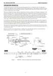
No. SS2-SLX100-0100 Azbil Corporation - 2 - OPERATION PRINCIPLE One side of the torque tube is fixed onto the torque tube housing with screw. And the other side of the torque tube is assembled with torque arm, which is supported at the knife-edge supporting point. When installing or using the level measurement, suspend the float on the edge of the torque arm, and then the torque tube will be twisted by the float's weight. Use the level measurement in this condition. When process liquid level changes, buoyancy will generate on the float according to the “Principle of Archimedes”. (Displacement type float is heavy. Therefore, float displacement may not change the level despite of the liquid level change. In general, it is designed as to be “generated buoyancy of liquid level at 100 % < float mass”). The proportionally generated buoyancy to the level, converts into torque by torque arm/knife-edge which suspends the float, and to the torque tube. Torque tube functions as to enclose the process liquid and as torsion spring function, and converts torque into angle displacement. This angle displacement transfers through torque rod and coupling, and detected by the angle displacement sensor. Then, it will be converted into liquid level signal by A/D converter, and sent it to CPU. In case the process liquid contacts with torque tube, the shearing module of the torque tube material will be changed by liquid temperature, and then changes the torsional spring constant, and generates the output shift. To compensate the output shift, which generates by liquid temperature, temperature around the torque tube is detected by the temperature sensor, converted into temperature signal by A/D converter and then sent to CPU. These liquid level signal and temperature signal are computed by CPU, and become digital signal based on each configured range by the communicator. This computed value will be converted into 4 to 20 mA DC analog signal with D/A converter and will be output. Moreover, model SLX is provided parameters to compensate the output shift which generates by liquid temperature. (Default parameters are set at shipment, can be set using the communicator later.) Figure 1 Model SLX - Structure of signal route and signal block diagram Torque arm Float Knife-edge Case Coupling Shaft bearing Torque rod Temp. sensor Torque tube Angle sensor Extension Torque tube housing Extension assembly Measurement assembly Torque tube housing assembly Float assembly Liquid level Measurement liquid (electric circuit) 4 to 20 mA 0 to 100 % Liquid level (specific gravity) 0 to 100 % angle D/A CPU A/D sensor coupling Torque rod Torque tube Torque arm / Knife-edge Float Output Input Temperature sensor Temperature Voltage Voltage (Angle) (Angle) Angle Torque Buoyancy