fi-09 27 / 36
10秒後にBOOKのページに移動します
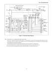
No. SS2-APN100-0100 - 4 - Figure 1. Functional Block Diagram Note 1. Shorted when “Yes” is selected for limit switch contact output. When “Yes” is selected for limit switch contact output, it is recommended to cut off the UP and Down input pulse signal at the limit values (limit H and Limit L) using an external sequence circuit. Excessively high input pulses cause hitting of the mechanical stopper and chanttering of the worm gear mechanism. The ball bearing of the worm gear shaft will be destroyed by long-term operation in a chattering state. 2. This is the wiring when “No” is selected for limit switch contact output. M2 can be added only in this case. 3. Be sure to disconnect the jumper plate to perform withstand voltage and insulation resistance tests.