Precision sensors for real-time position measurement with 0.1 ㎛ accuracy
High-precision position sensors
As successors to Azbil’s edge detection sensors, which precisely determine the position of glass and film edges, high-accuracy position sensors that deliver even more accurate and fast measurements have been added to the product lineup. The new sensors achieve a measurement resolution of ±0.1 µm and measurement cycle of 250 µs, placing them at the highest level in the industry. The sensor head is only 8 mm thick (7 mm measurement width model) and is easy to mount on various types of equipment. The position sensors are equipped with support for the MECHATROLINK-III and EtherCAT® field networks to facilitate product quality improvement.
Background and Needs
Highly rated top-performing edge detection sensors since 2004
In the process of manufacturing liquid crystal displays, edge detection sensors are essential for precise glass alignment and for prevention of meander by metal foil and film as they are rolled up.
Edge detection sensors literally detect the edge of an object and changes in its position. In addition to high accuracy (high resolution), high-speed processing that can keep up with the speed of glass transport or film windup is required.
In 2004, Azbil Corporation put its edge-detecting laser sensors on the market. By utilizing Azbil's unique Fresnel diffraction approximate correction algorithm [*1] , the sensors achieved superior performance, such as a measurement resolution of ± 0.1 ㎛. Their features include sensing of the edge of transparent glass.
The edge detection sensors can be mounted on various types of manufacturing equipment, for example roll-to-roll apparatus for electrode material for lithium-ion battery or LCD conveyors, and have been highly evaluated. Advances in manufacturing technologies, however, have created the need for higher accuracy and faster processing.
[*1] Our name for Azbil's unique sub-pixel processing, which utilizes Fresnel diffraction approximate correction.
Key Innovations
Tenfold increase in resolution and twofold in processing speed
By improving the specially designed optical and signal processing systems, we developed high-accuracy position sensors with enhanced measurement resolution and processing speed, while keeping the strong points of the preceding edge detection sensors. The new sensors became available in January 2015.
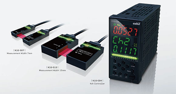
Exterior of the high-accuracy position sensors: the emitter and receiver of the 7㎜ measurement width model (left) and of the 15㎜ measurement width(center), and the controller (right).
By accelerating the calculating speed and enhancing the accuracy of the new position sensors, we were able to realize the extremely high measurement resolution [*2] of ± 0.1㎛, which is ten times the accuracy of the conventional sensors. With improvements like the introduction of parallel circuits to execute high-speed calculations, the measurement cycle was halved from 500 to 250 μs to support faster transport and winding. The moving accuracy [*3] is 20 ㎛ or less and the repeatability [*4] is ± 1㎛.
[*2] Measurement resolution: internal calculation resolution
[*3] Moving accuracy: when the target object is moving, the difference between the measured value and the actual amount of movement
[*4] Repeatability: fluctuation in measured values when a target object is positioned at a place and measured repeatedly multiple times under the same conditions
In spite of their enhanced performance, the sensor heads (emitter and receiver) remain as small as the previous sensors, allowing installation on equipment in various places. In addition, thanks to our unique digital interface, the cable connecting the sensor heads to the controller can be as long as 25 meters, allowing more flexible installation.
Furthermore, in addition to analog output, the new field network function is available for transferring measured data to other devices on the network. MECHATROLINK-III and EtherCAT®, which are open field network standards, are now supported. Measured data can be sent to the host control system at high speed, which reduces the number of cables needed and cuts the time required for installation and maintenance.
Detecting edges by utilizing physical phenomena of light and processing measured data by a curve fitting method
The core technology of Azbil's high-accuracy position sensors is Fresnel diffraction approximate correction.
The most simple method of sensing the edge of an object optically is to project light (a collimated laser beam, etc.) onto the object and, by using an imaging sensor, to detect the border between the lighted part and the shaded area blocked by the object. However, an imaging sensor with a fine pixel pitch is required by this method, because the detection accuracy (resolution) depends on the resolution (pixel pitch) of the imaging sensor. In addition, the border of light and shadow is blurred due to a physical phenomenon called diffraction, which is explained below, making precise determination of the edge position difficult. Furthermore, transparent objects are difficult to detect because there is not much difference in the amount of light (light intensity) between the lighted and shaded areas.
To solve these problems, Azbil adopted a unique edge detection method that utilizes a characteristic of light called Fresnel diffraction. Diffraction is a phenomenon in which the light that passes an object's edge or through a slit bends around into the shadow and is then distributed. Diffraction observed when the distance between the object and the surface of projection (the receiving sensor head) is relatively short is called Fresnel diffraction.
When collimated light is projected onto an object having a pointed edge, for example a knife-edge, and when the surface of projection is relatively close to the object, the human eye can distinguish only light and shadow, but not the amount of light on the surface. By technical means, however, data on the light intensity on the projection surface can be represented by the curve in Figure 1. The curve goes up steeply at around a light intensity of 0℅ just before the edge of the target object, and the light intensity exceeds 100℅ Then it goes down and up repeatedly and converges to 100℅. This characteristic curve of light intensity can be expressed in an equation (Equation 1).
In principle, if the light intensity data obtained by an imaging sensor is actually plotted on a graph, the curve calculated by Equation 1 or the curve illustrated in Figure 2 is drawn. Conversely, by calculating a likely (best matching) curve using Equation 1 for the data of several points actually obtained by an imaging sensor, it should be possible to determine the point that indicates the edge position. This method is generally called curve fitting or curvilinear regression, and is used for purposes like calculating unknown parameters of an equation that seems correct for the measurement in theory or by experience.
However, the complex function of Equation 1 cannot be solved analytically. Using it for the light intensity data obtained by an imaging sensor would require a huge amount of calculation, and it would be impossible to increase the processing speed, which is a critical requirement for edge detection sensors. Because the edge position is projected to the area of 25℅ light intensity, which is the rising section of the Fresnel diffraction waveform (Figure 2), we noticed that considering only the rising section would be enough to detect the edge position, and we devised an approximate equation described below (Equation 2), which is simpler than Equation 1 and can be solved analytically.
The significance of this approximate expression is that the edge position can be estimated by calculating x, which puts several points from the rising section of the light intensity data (Figure 2) obtained by the receiver's imaging sensor on this curve. Azbil called this idea "Fresnel diffraction approximate correction" and introduced it into the development of edge detection sensors.
Another advantage of using Fresnel diffraction approximate correction is that high-resolution imaging sensors are not required for detection. Imaging sensors with only 128 pixels are used for the 7㎜ measurement width model of the high-accuracy position sensor to achieve 70,000-point measurement resolution (7㎜ ÷ 70,000 = 0.1㎛), and 256-pixel imaging sensors are used for the 15㎜ measurement width model to realize 150,000-point resolution (15㎜ ÷ 150,000 = 0.1㎛) when using the above-described equation.
(Equation 1)
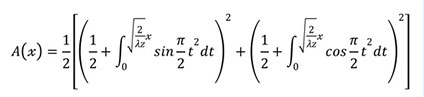
where λ is the wavelength of light and z is the distance between the target object and the light-receiving surface
(Equation2)
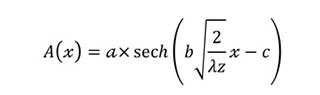
where a, b, and c are coefficients and fixed values
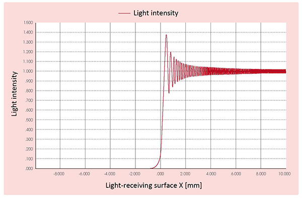
Figure 1. Example of characteristic curve of light intensity on the light-receiving surface (surface of projection) caused by the Fresnel diffraction phenomenon (horizontal axis: the position of the light-receiving surface, vertical axis: light intensity The edge of the object is at 0 mm and the object is on the negative side of the light-receiving surface (left side of the graph.)
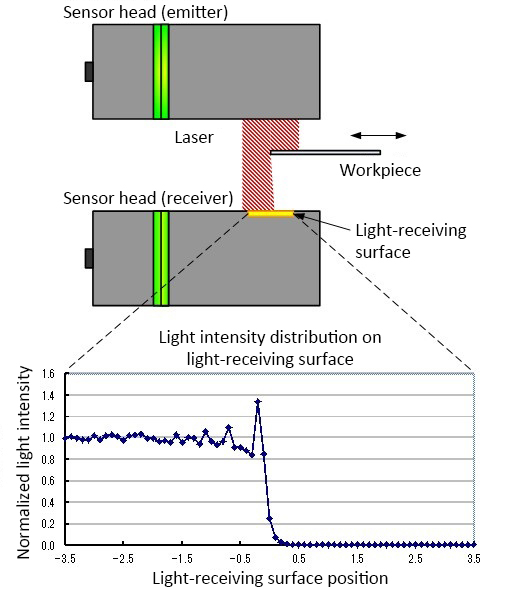
Figure 2. Illustration of intensity of received light
Results and Future Outlook
Helping to improve manufacturing quality by providing multipurpose high-accuracy position sensors
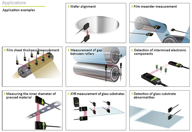
Our high-accuracy position sensors can be used for various purposes, such as glass alignment and film meander prevention, that were mentioned above. Other applications include semiconductor wafer alignment, film thickness measurement, measurement of the gap between rollers, detection of foreign matter or intermixed components, inner diameter measurement, and detection of breakage and cracks (Figure 3).
These sensors make fast and highly accurate measurement possible and can detect phenomena predictive of problems in order to prevent the production of a defective product. Its features meet the needs of customers who are moving ahead with product quality improvement. We believe that our high-accuracy position sensors will contribute to improving the quality of production at their plants.
Azbil continues to make every effort to provide excellent solutions in accordance with our corporate philosophy of human-centered automation.
Figure 3. Various applications of high-accuracy position sensors
MECHATROLINK is a trademark of Yaskawa Electric Corporation.
EtherCAT® is a registered trademark and patented technology licensed from Beckhoff Automation GmbH, Germany.
*Handling of products and services described in “azbil techne” may differ by country or region.
azbil Technical Review
Industrial Sensor Networking Technology for Improvement of Manufacturing Equipment Effciency