Valve positioner with diagnostic functions for detecting valve abnormalities and signs of deterioration
Smart valve positioner
Azbil Corporation, which provides the global market with valve positioners to control valve flow rate, has recently announced the development of its 700 Series smart valve positioners, which offer enhanced functionality and maintainability, in keeping with Azbil's corporate philosophy of “human-centered automation.” While maintaining the high reliability and robustness of the preceding models, which have sold over a half million units, we have improved the auto-setup function and diagnostic functions.
Background and Needs
Providing more intelligent, digitally controlled valve positioners for the global market
At oil and chemical plants, as well as steel, pulp, food, and pharmaceutical plants and other industrial facilities, valves are installed on pipes in order to control the flow rate of gases or liquids. Hundreds of valves are used at a small facility and thousands are necessary at a large facility.
The host control system controls the opening and closing of these valves and adjusts the degree of opening (travel), and valve positioners physically move the valves (Fig. 1). Valve positioners supply compressed air to the actuator (a mechanical part of the valve), detect the valve travel from the position of the valve stem, and adjust the air pressure to keep the proper travel as commanded by the control signals, which are generated using feedback control.
The function of valve positioners at first glance seems simple, but in fact positioners need to internally calculate correction for the detected stem position of valves, each of which has different full-open and full-close positions. Functions such as detecting the difference between the set travel and actual travel are also necessary. In addition, long-term reliability and robustness in various environmental conditions from cold to extremely hot (desert) climates are required.
Azbil Corporation has long been providing mechanical (analog) valve positioners. In 1998, we started selling smart valve positioners featuring digital control. The 300 Series of smart valve positioners, our signature products, have already sold over half a million units and are used at plants or factories in Japan and around the globe.
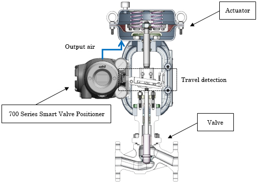
Figure 1. Cross-sectional view of a valve
Key Innvations
Greatly enhanced performance with three key improvements
Azbil Corporation developed 700 Series smart valve positioners as an improved version of the 300 Series and started shipment in March 2014 (Feb. 2015 for TIIS pressure-resistant explosion-proof certified models). 700 Series positioners were developed to reflect the azbil Group's philosophy of "human-centered automation."
The features of the 700 Series include shorter auto-setup time for faster on-site operation startup, enhanced diagnostic functions allowing inexperienced users to inspect control valves, and functions providing safer and easier adjustment and setup even in explosive atmospheres. By improving these functions, which greatly affect human operations, we hope to contribute to safe and reliable plant operation and a better on-site work environment. The improvements are outlined in the following sections.
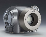
700 Series smart valve positioners
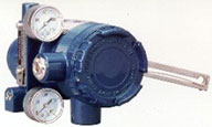
300 Series smart valve positioners
Focusing thoroughly on the functionality of controlling and diagnosing control valves and likening the positioners to the brain, we created an organic design for 700 Series positioners (left photo above) that calls to mind the human brain. Because of its characteristic design, the 700 Series won the Review Committee Special Award in the 45th Machine Design Awards held in July 2015, which was sponsored by the Business & Technology Daily News (Nikkan Kogyo Shinbun). Compared to the 300 Series (right photo above), its curved surface has a beautiful design and creates the impression of substantiality.
- Simpler setup
Positioners are used with various types of valves. Setup is necessary after installation so that the positioner can learn the valve's full-open to full-close range of positions and the relationship between the air pressure supplied to the valve and the amount of travel.
Azbil implemented the auto setup function on the 300 Series ahead of its competitors, and the function has been greatly appreciated by customers. We refined the auto setup function for the 700 Series, shortening the time required for setup from 120 seconds for the 300 Series to just 45 seconds.
Most of the auto setup time is used by executing a full stroke of the valve. The 300 Series needs to perform three full strokes. The 700 Series needs only two full strokes, which was made possible by storing valve positions during a full stroke and the elapsed time in a large capacity memory, and referring to this data later.
To set up positioners automatically, functions for determining control parameters and obtaining initial diagnostic information are required. We invented a valve operation method from which various types of information necessary for these functions can be extracted with the needed accuracy. This method consists of reciprocating micro ramping at two intermediate travel points (Fig. 2). From the reciprocating micro ramping performed with the optimum width and speed, it is now possible to measure a quasi-static state (control output, nozzle back pressure, output pressure, and travel) near the operation points.
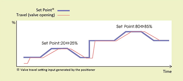
Figure 2. Reciprocating micro ramping at two intermediate travel points
- Enhanced diagnostic functions
At plants and factories, it is extremely important to keep valves and valve positioners in a sound condition, and regular inspection and adjustment are essential. However, it is not easy to manually inspect each of the many valves and positioners scattered throughout an extensive site, which would increase maintenance costs.
The 700 Series has improved diagnostic functions that enable users to detect valve abnormality and signs of deterioration while the valves and positioners are operating. Furthermore, 700 Series positioners are equipped with a function for detecting an abnormality in their own functioning.
Various diagnostics are available, including force balance diagnosis to determine whether the forces related to the valve (fluid pressure, spring power, etc.) are properly balanced, and stick-slip diagnosis to detect sticking and slipping on the sliding surfaces.
The 700 Series has four pressure sensors that are not found on the 300 Series. It is rare that a valve positioner has so many pressure sensors. Normally the addition of four sensors would increase power consumption, but we solved this problem by supplying power to each sensor only when it is in use.
The pressure sensors make possible the air circuit diagnosis and force balance diagnosis (monitoring output air pressure [PO] validity and maximum friction). These newly added diagnostics for the 700 Series are not available on the 300 Series. Static characteristics data are acquired for diagnosis by collecting only data for small amounts of change per unit time.
The air circuit diagnosis uses an algorithm for detecting oil or water accumulation in the positioner due to facility problems or other causes. By means of the PO validity monitoring for force balance diagnosis, problems of the components that control air pressure (deterioration and falling of a spring, etc.) can be detected. With maximum friction monitoring, problems such as gland packing deterioration, hardening, or softening can be diagnosed.
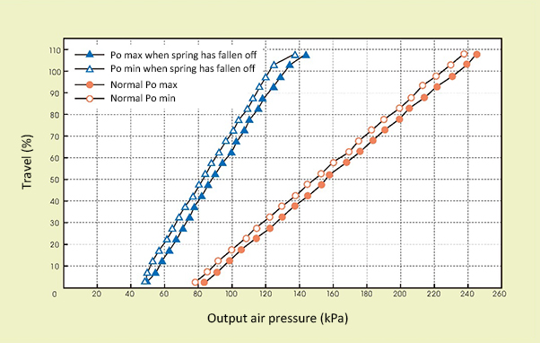
Figure 3. PO validity monitoring data in a case when an actuator spring has fallen off
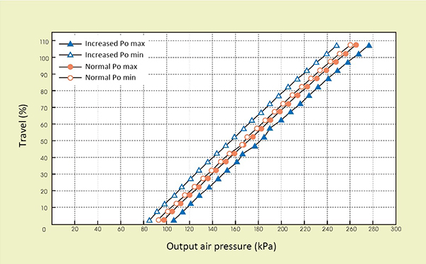
Figure 4. Maximum friction monitoring data when a gland packing abnormality, etc., has occurred
The 700 Series supports the latest de facto communication standards for industrial plants. The positioner can be connected to any host system and provides continuous reliable communications. The results of diagnoses made by the 700 Series are sent to the host system to be utilized for predictive maintenance. We believe that maintenance costs can be reduced by shifting from time-based maintenance to condition-based maintenance.
- Easier on-site operation
We implemented a local user interface (LUI) on the 700 Series so that setup and diagnosis can be performed on the site as well as from the control room. Inside the front cover there are four buttons for selecting menus and a liquid crystal display. Users can execute auto-setup before starting operation, set control parameters, check diagnostic information, display supply air pressure or output air pressure, select manual operation of the valve, etc.
The 700 Series has acquired pressure-resistant explosion-proof certification issued by the Technology Institution of Industrial Safety (TIIS) [*1] and other explosion-proof certifications from around the world. If somehow the internal circuits of the valve positioner would emit sparks, there would be no effect outside the positioner, and the plant would remain safe. Setup can be performed safely even in an explosive atmosphere.
The push buttons for changing settings are not electrical switches, as is usually the case. Instead, the operational signals are relayed to the internal circuits using magnets outside the housing and magnetic sensors inside the housing. Because of this mechanism, it is possible to operate the positioner while meeting the pressure-resistant explosion-proof requirements and keeping the housing well sealed. Generally speaking, magnetic control is difficult, and the risk of malfunction is high, depending on the design. Azbil, with its excellent design capabilities, has succeeded in mounting the magnetic sensors (switches) of the 700 Series close to one another, keeping a long distance from the magnets. The distance between the sensors (switches) is approximately 2㎝ while the distance between the magnets and sensors is about 3㎝.
[*1] A public-interest incorporated association that certifies the safety of explosion-proof devices used at factories in Japan.
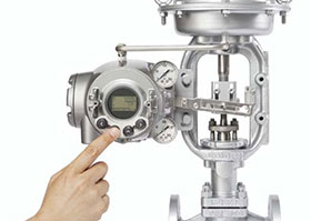
The local user interface of the 700 Series
Results and Future Outlook
Supporting customer's plants and factories by providing products with human-centered value
The 700 Series, whose features are partly introduced above, has already been installed in the plants of customers in Japan. In January 2016, we started selling an SIL-certified[*2] model and will expand our product lineup to meet various customer needs. Sales to large oil plants in oil-producing countries are also scheduled.
Azbil also provides application software called PLUG-IN Valstaff[*3] for online monitoring and inspection of valves and valve positioners (Fig. 5)
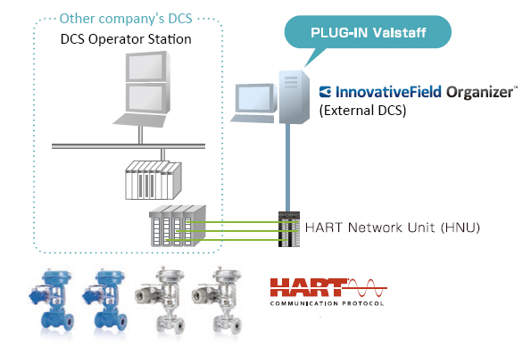
Figure 5. Example of PLUG-IN Valstaff system configuration
[*2] SIL (Safety Integrity Level) indicates a system's safety performance. It is defined in IEC 61508 (an International Electrotechnical Commission standard). There are a total of four SIL levels, from SIL1 to SIL4.
*Handling of products and services described in “azbil techne” may differ by country or region.
azbil Technical Review
Development of New Smart Valve Positioners for Enhanced Safety of Plant Operations