Flow-Measuring Control Valve Saves Energy
ACTIVAL+™ motorized control valve with flow measurement and control functions
In 2009, Azbil developed the ACTIVAL+™ motorized control valve with flow measurement and control functions for use in building air conditioning systems. In contrast to conventional control valves that can only control their degree of opening, ACTIVAL+, which has a flow rate measurement function built into its compact body, can control the flow rate of chilled or hot water according to the properties of the coil (heat exchanger) of the air conditioning system. ACTIVAL+ is highly rated for its ability to conserve energy and visualize energy consumption of building air conditioning.
Background and Needs
Excessive flow rates beyond the capacity of the heat exchanger cause problems.
Efforts to conserve energy are progressing in many different fields. Further energy conservation is especially needed in the business sector, where office buildings, commercial buildings, hospitals, and schools consume large amounts of energy.
Azbil has focused its attention on conserving the energy used for transport in building air conditioning systems. A building air conditioning system circulates water chilled by chillers or hot water heated by boilers, generates cool air or warm air with the coil (heat exchanger) using the chilled or hot water, and supplies the air to each floor or zone. It had been pointed out that the performance of the heat exchanger plateaus after a certain flow rate due to the nature of coils, and that flow in excess of that rate is wasted (fig. 1).
Although fine control of the flow rate of chilled or hot water in line with the characteristics of the coil is ideal, conventional valves can control the degree of valve opening, but cannot control the flow rate directly. Of course, a flowmeter could be added to each AHU for better flow rate control, but in that case a longer pipe would be needed, leading to installation space problems and increased costs.
To solve these problems, Azbil developed ACTIVAL+ in order to measure and control the flow rate with high accuracy (fig. 2). One feature of this product is the compact integration of the valve, actuator, and flow rate measurement control function.
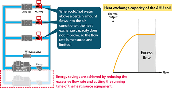
Fig. 1. Configuration of the central air conditioning system (left) and graph of the heat exchange capacity of the AHU coil (right)
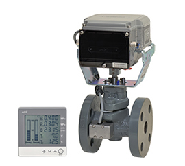
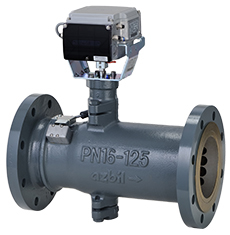
Azbil has also developed a large diameter ACTIVAL model (right) for large-capacity air conditioning systems. An optional display unit that shows the flow rate and the open position of the valve is also available.
Key Innovations
Realization of high-accuracy differential pressure measurement throughout the whole range of valve opening positions
From among the many different measurement methods used by flowmeters, ACTIVAL+ employs the differential pressure method. The principle of this method is as follows: when a perforated plate (an orifice) is placed inside a pipe oriented perpendicular to the flow, the pressure downstream of the orifice becomes lower than that upstream. The flow rate can be calculated from the difference using Bernoulli's principle.
When developing ACTIVAL+, Azbil set the goal of incorporating a flow rate measurement function without changing the size of the valve, and so decided to use the pressure difference before and after the plug that adjusts the flow rate. Along the way, we solved the following three technical challenges.
1. Reliably measuring the pressure upstream of the plug. 2. Reliably measuring the pressure downstream of the plug. 3. Accurately identifying the properties of the flow that vary according to the position of the plug (degree of opening).
- Pressure measurement upstream of the plug
A non-straight pipe such as an elbow or reducer may be installed near a valve because of the layout of the building air conditioning system piping. We checked the effect of this with computational fluid dynamics [*1] and found, among other things, that a pressure variation of up to about 4 kPa occurs at the valve inlet if a 90-degree elbow is connected immediately before the valve (fig. 3).
[*1]I.e., solving fluid equations to calculate the state of flow in a certain space using a computer.
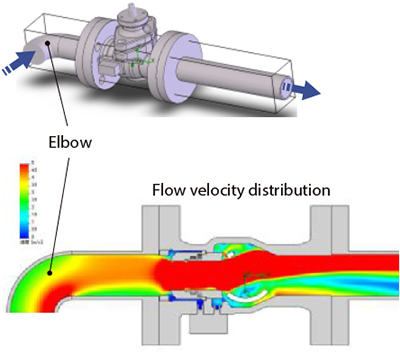
Fig. 3. Upstream pressure measurement
General flowmeters require a preceding straight pipe that is five times as long as the pipe diameter to eliminate the effects of uneven flow caused by an elbow or other upstream component. However, such a long pipe imposes limitations on installation, etc. We reasoned that high-accuracy measurement should be possible without adjusting the flow if the pressure is averaged at multiple points inside the pipe. Accordingly, we adopted a valve structure with four ports for pressure measurement. The ports are internally connected, and the average of their pressures is calculated, rather than only measuring the pressure at the valve inlet (fig. 4).
We created a test valve with this structure and compared the flow rates with a straight pipe and with an elbow. Because the measurement error was 0.7 % or less, this structure proved to be effective.
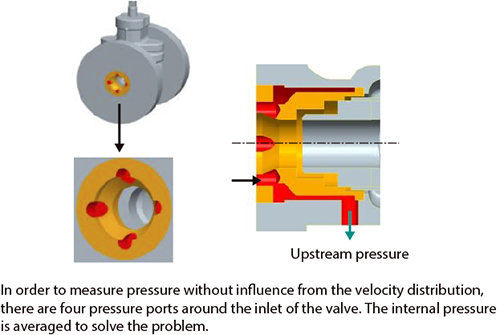
Fig. 4. Structure of the upstream pressure measuring component
- Pressure measurement downstream of the plug
Because the flow through the valve changes depending on the degree of opening, we used computational fluid dynamics to check the flow inside the valve when the amount of travel was changed (fig. 5). As a result, behind the plug we found a dead water zone where the pressure is not affected by the flow even when the degree of opening changes. We focused our attention on this point as it is a place where the pressure downstream of the plug can be reliably measured.
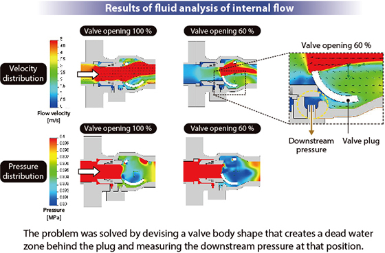
Fig. 5. Downstream pressure measurement
- Cvv table according to the degree of opening of the valve
The size (open area) of the orifice does not change in normal differential pressure flowmeters. However, it effectively changes depending on the degree of opening if the valve plug is regarded as an orifice. So, even if the differential pressure can be measured, it cannot be directly converted into the flow rate.
The size (open area) of the orifice does not change in normal differential pressure flowmeters. However, it effectively changes depending on the degree of opening if the valve plug is regarded as an orifice. So, even if the differential pressure can be measured, it cannot be directly converted into the flow rate.
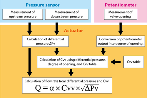
Figure 6. Overview of the flow measurement algorithm used by ACTIVAL+
In addition, variations in dimensions and the assembly of parts affect the Cvv and therefore the accuracy of flow measurement. To ensure consistent high flow measurement accuracy, Azbil conducts a flow rate inspection before shipping the product to compensate for these variations and guarantee accuracy.
By applying all of these techniques, we have made high-accuracy flow measurement possible across the whole range of valve opening without making the product larger than a conventional control valve.
Results and Future Prospects
Demonstration of the energy efficiency of the chilled/hot water pump in an Azbil office building
Azbil installed a system using ACTIVAL+ into the HVAC equipment at the Fujisawa Technology Center (in the city of Fujisawa in Kanagawa Prefecture) as an experiment to check its energy-conservation effectiveness.
The heat exchange performance of the coil in the facility peaks at around 80 liters per minute. However, more than 100 liters of chilled or hot water might have passed by every minute if the flow rate was controlled only by the degree of opening, resulting in wasted flow.
We operated ACTIVAL+ in this system by setting 80 liters per minute as the upper limit for the experiment and successfully reduced the power consumption of the chilled/hot water pump by 8 % during heating and 12 % during cooling, since it was no longer necessary to supply chilled/hot water beyond the performance of the coil (fig. 7).
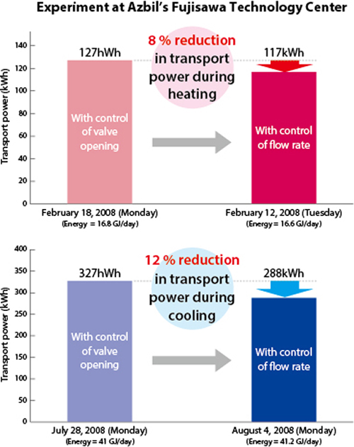
Figure 7. Result of energy conservation experiment at Azbil’s Fujisawa Technology Center office building using ACTIVAL+
This experiment shows that energy can be automatically conserved by merely setting the maximum flow rate based on the capacity of the coil while visualizing energy consumption by installing ACTIVAL+. ACTIVAL+ can be installed in the same space as a conventional valve, and installation costs can be recovered through energy conservation. For these reasons ACTIVAL+ is highly appreciated by offices that design air conditioning systems, HVAC equipment companies, and other users.
ACTIVAL+ received a 2015 Technology Award from the Society of Instrument and Control Engineers for its originality. With measurement and control as its strong suit, Azbil develops and offers high value-added solutions that meet energy conservation needs.
*Handling of products and services described in “azbil techne” may differ by country or region.
Related Information
ACTIVAL+™ motorized control valve with flow measurement and control functions