A Vial Loading System with Non-Contact Drive Mechanism Using Magnetic Technology
キーワード:non-contact, magnetic driven, compact layout, good manufacturing practices (GMP), Food and Drug Administration (FDA), automatic vial loading and unloading system, pharmaceutical manufacturing, freeze drying system, magnetic lead screw, clean transport system
近年、医薬品の凍結乾燥装置の分野において自動搬送装置の需要は高まってきている。製品品質が直接人体に影響を及ぼすことから、このような製造装置には高い清浄度、無菌状態を維持することが求められる。従来はシリンダ式のプッシャやベルト式の搬送装置が利用されているが、これらはベローズやガイド構造に狭小な溝を有するため洗浄性が悪く、また装置の滅菌処理に課題があった。Azbil Telstarでは従来の送りねじに替え、磁石で作られたナットと磁性材によるねじ軸とが磁気的結合力により非接触で駆動力を発生させる磁気ねじを用いた新しい自動搬送装置を開発した。ねじ軸は表面が平滑なステンレスカバーで封止され、ナットを搭載したスライダがチャンバ内外に設置されたねじ軸に沿って移動して製品を搬送する構造で、ベローズカバーを不要とした洗浄作業性の向上、チャンバ内に移動するすべてのパーツを炉内で蒸気滅菌できる無菌性の向上、そしてRear Pusherの廃止とFront Pusherの短縮による装置の小型化を実現したのでここに報告する。
1.Introduction
Azbil Telstar has more than 50 years of experience in designing and manufacturing freeze drying machines for pharmaceutical production. This kind of machine uses loading systems that can be operated manually, semi-automatically, or fully automatically in order to handle vials containing pharmaceutical products. Although an automatic loading and unloading system requires a high initial investment and much space for the machine, it has the advantage of cost reduction by decreasing the number of operators in the cleanroom, raising productivity by reducing operation cycle time, and maintenance of quality. It can also free operators from hard work and allow toxic products to be handled more safely in isolators. Recently, customers tend to prefer freeze drying machines with automatic systems.
In designing this kind of machine, manufacturers must follow good manufacturing practices (GMP), a compendium of regulations enforced by regulatory authorities for the pharmaceutical industry, such as the U.S. Food and Drug Administration (FDA). GMP guidelines cover quality management systems, the quality of raw materials, design considerations, robust operating procedures, etc., in order to assure the quality and purity of manufactured pharmaceutical products.
Automatic systems have matured and the technology employed by different manufacturers has not evolved much recently. However, current proprietary systems still have room for improvement in terms of GMP and their large footprint, so customers are not fully satisfied with systems currently on the market. Taking customer requirements into consideration, Azbil Telstar has developed a new automatic loading and unloading system with a patented non-contact magnetic drive mechanism. It is very compact and easily integrated with isolators and a restricted access barrier system (RABS), which has a physical barrier to restrict access and a controlled one-way airflow to keep the area clean by means of a HEPA filter. Therefore, compared to similar systems, our new automatic loading and unloading system ensures GMP by improving cleanability and sterility.
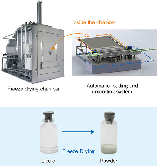
Fig. 1. Freeze drying machine
2.Current Automatic Vial Loading Systems
In the following, the details of Azbil Telstar’s two main automatic vial managing systems are described.
2.1. Push-push system
Pusher + Colt:
This option consists of a long pusher in front of the machine that loads vials row by row, until the final push completes loading of the full shelf. To unload vials, there is a rear pusher (called a Colt), that works with several rods encapsulated in a revolver drum, which are released and coupled one by one. This configuration makes the machine more compact, but is more expensive and complex. In a push-push configuration, it is also possible to replace the Colt with a long rear pusher, but this option is not very common.
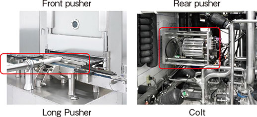
Fig. 2. Pusher + Colt system
2.2. Push-pull system
Pusher + Belt:
In the pusher + belt configuration, instead of a rear pusher (a Colt or rear long pusher) there is a belt mechanism. As in the push-push system, a front long pusher is used in the loading phase. A belt which has a bar for handling vials, and belts connected to the bar on both sides, are used in the unloading phase to pull vials out of the chamber. This system is more compact than the rear pusher.
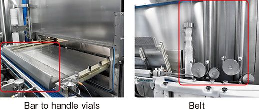
Fig. 3. Pusher + belt system
2.3. Opportunities for improvement in current systems
Azbil Telstar’s current automatic loading and unloading systems are well known and are used in many freeze drying machines. However, both systems can be improved to the benefit of customers. The main improvements needed are: better adherence to GMP, reduced footprint, decreased maintenance operations, and easier cleaning by automatic procedures.
In the push-push system, points that can be improved are the use of bellows and the need for a large installation space. Bellows are spring-like components made of plastic or stainless steel that compress and extend during normal operation. They are needed to fully cover linear movement which can potentially generate particles. Since bellows have narrow grooves, they are difficult to clean completely and there is always a risk of remaining contamination. Also, the system has a long pusher in front, which restricts the workspace of operators. Moreover, it makes the design of isolators and open or closed RABS more complex due to the necessity of sealing the long pusher. The Colt is a compact pusher composed of a revolver drum with several discrete rods (bullets) that connect to each other to form a long pusher. It is installed in the back of the machine. This system restricts the design of the condenser of the freeze drying machine. A desirable improvement would be to remove the bellows and pusher from the system or to reduce the length of the pusher.
With regard to the belt system, there is a mechanism that guides belts into the machine properly. Since the belt is a thin sheet of metal, the belt guiding system has very narrow grooves. Therefore the belt guiding system is very difficult to clean and sterilize completely. A desirable improvement would be to remove any narrow grooves like those of the belt guiding system. Fig. 4 shows the labeled subsystems.
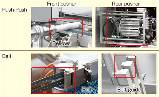
Fig. 4. Points for improvement in current systems
3.Magnetic Lead Screw
3.1. Difference from a conventional lead screw
Lead screw transmission is widely used in automatic transport systems in order to position an object linearly with high accuracy. However, in the case of a system which needs great cleanliness during operation, such as in pharmaceutical manufacturing processes, there is a GMP restriction on using this technology because contact between the screw and nut generates particles. Additionally, grease is normally used, so there is considerable risk of contamination. To avoid these problems, a conventional lead screw requires some kind of modification for clean applications, such as covering it with a bellows. However, there are important concerns and limitations with regard to bellows, including maximum allowable stroke, periodic maintenance, difficulty of cleaning, and increased cost.
By contrast, an actuator called a magnetic lead screw, which transfers the drive force by magnetic coupling, has previously been studied and developed. It can solve the problems of the lead screw because there is no contact and therefore no particle generation. However, a magnetic lead screw has less ability to transfer force, and is less rigid than a mechanical lead screw, so the design must take these characteristics into account. On the other hand, the nature of magnetic technology allows misalignments to occur without breaking any mechanical component.
3.2. Principle
Next we describe the structure of the magnetic lead screw that was developed for the new system. It is composed of a screw shaft and a nut. The screw shaft is made of ferromagnetic steel and has threads with a certain pitch and shape. The nut is composed of neodymium permanent magnets which are magnetized spirally with the same pitch as the threads of the screw shaft. There is a yoke at the periphery of the nut (magnets) in order to close the loop of the magnetic circuit. The screw shaft is supported by bearings at both ends so that it can rotate. The nut is supported by a guide mechanism so as not to rotate but to be movable along the axis. It is most stable when the magnetic poles of the nut face the threads of the screw shaft. When the screw shaft is rotated it generates a relative displacement between the magnetic poles and the screw threads. Thereupon a restoring force is generated which acts to restore a stable position by magnetic coupling. By that means the nut moves linearly following the rotation of the screw shaft.
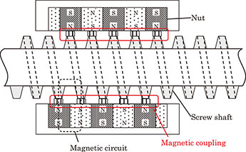
Fig. 5. Stable position of the magnetic lead screw
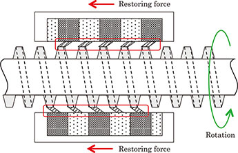
Fig. 6. Restoring force by relative displacement
It is difficult to calculate the restoring force because adjacent magnetic couplings possibly interfere with each other, and the magnetic circuit in the magnetic lead screw is complex. Therefore the restoring force has been calculated with the finite element method (FEM). The relationship between restoring force and relative displacement is shown in Fig. 7. According to calculations, peaks in the restoring force occur at a relative displacement of 45° and in the opposite direction at 135°. There is no restoring force at a relative displacement of 0, 90 or 180°. Because we used a double threaded screw as the screw shaft, if the relative displacement reaches 180°, the magnetic pole of the nut couples with the next thread of the screw shaft. Therefore it is assumed that this will repeat at a cycle of 180°. To use this mechanism for a transport system it is important to consider whether the peak thrust force is sufficient for transport, and the effects of rigidity on positioning accuracy.
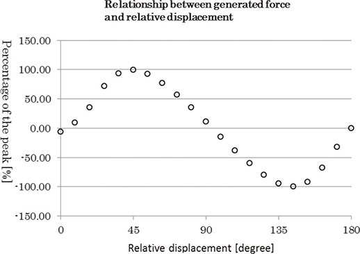
Fig. 7. Relationship between generated force and relative displacement
4.Verification Test Bench
4.1. System configuration
To verify the performance of the new system, a full-scale test bench capable of simulating the sequence of loading vials from conveyor to shelf and unloading vials from shelf to conveyor was constructed. The following shows the structure of the test bench.
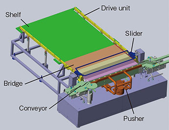
Fig. 8. Test bench configuration
It is composed of different subsystems, including the following.
- Shelf
A place where loaded vials are placed. It represents the interior of a freeze drying machine chamber. - Conveyor
Used for transporting vials in a loop to perform endurance tests. - Bridge
Serves as an intermediary for transporting vials between the conveyor and the shelf. It can be separated in order to close the chamber door. In this prototype the chamber door has been omitted. - Pusher
Used to push vials from the conveyor to the bridge. - Drive unit
Composed of the screw shaft of the magnetic lead screw and the guiding system for the slider. It runs along both sides of the shelf and bridge, and is composed of different assembly groups which can be connected to and disconnected from each other. - Slider
Contains the nut of the magnetic lead screw and can be moved from bridge to shelf. It has a long bar that spans the bridge or shelf and is used to pull or push vials. - Buffer unit
(Not shown.) A rotary table is used to store vials, and is connected to the conveyor so as to implement a continuous loading and unloading sequence.
The sequence of loading and unloading vials is as follows. First, vials are transported from the buffer unit and are lined up on the conveyor. Next, the pusher pushes a row of vials out of the conveyor and goes back to standby position. These steps are repeated until all the vials are unloaded from the conveyor. In this situation, some of vials are on the shelf, but others are still on the bridge, since the pusher does not have a long stroke. The slider then moves to the end of the bridge and pulls the vials with the bar to complete the loading of the shelf.
In the unloading operation, the slider first moves to the end of the shelf. Next, it pulls vials off the shelf in the direction of the conveyor.
4.2. Improvements achieved
In this section the improvements achieved by the new system using a magnetic lead screw are discussed.
First, the system is more cleanable. It is important to remove small grooves and holes from the system because they are difficult to clean and may contain contaminating particles. Because there can be a gap between the screw shaft and the nut, the screw shaft can be fully covered with a stainless steel pipe (standard steel is not acceptable in GMP areas). Then, since only a short stroke is needed, the pusher does not require covering by a bellows, because linear motion is achieved by a rotary mechanism with rotary seals. In this way the system with a magnetic screw, which has a round shape and smooth surface, is more cleanable.
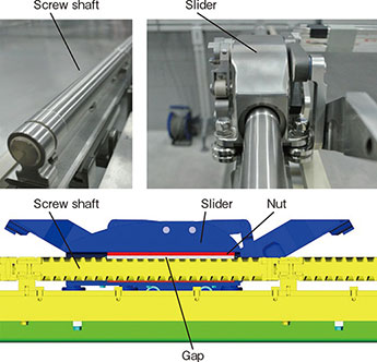
Fig.9. Magnetic lead screw as part of the system
Second, the system provides steam sterilization and cleaning in place (CIP) of the slider in the chamber. Steam sterilization is widely used for sterilizing freeze drying chambers because it does not require special chemicals, and the process takes less time than other methods. No power cable, signal cable, or other wiring is needed for control of the slider, and it can stay inside the chamber when the chamber door is closed. The slider is composed of material such as stainless steel and FDA-approved plastic parts that have good temperature and corrosion resistance characteristics. Therefore the slider can withstand chemical cleaning and steam sterilization processes.
Many automatic loading and unloading systems are manually cleaned by the operator, but this is a difficult job. It also carries the risk of contaminants remaining in the system, depending on the ability and tools of the operator. The availability of steam sterilization and CIP in the chamber helps to maintain quality and relieves the operator of hard work.
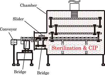
Fig. 10. Sterilization in the chamber
Third, the new system is compact. Because the slider loads vials from the bridge to the shelf, the pusher does not need the long stroke of the current system. That makes the system compact and makes it possible to prevent the parts of the pusher from hanging over the cabinet in front of the conveyor and to eliminate the rear pusher (such as a Colt or long rear pusher). This gives users a better work space and affords flexibility of layout.
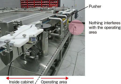
Fig. 11. Compact Layout
5.Conclusion and Future Prospects
The new and revolutionary automatic loading and unloading system we developed for freeze drying machines is a valuable upgrade to state of the art solutions. Its unique and patented design with a non-contact magnetically driven slider assembly and a compact front pusher that fits in easily with isolators and closed RABS, together with the absence of a bellows, the elimination of the rear pusher and belt mechanisms, the possibility of sterilizing all parts that go inside the chamber and in contact with the product, and its inherent simplicity, cleanliness, and reliability make this development a good asset for the pharmaceutical industry.
Azbil Telstar expects this newly developed system to provide current and new customers in the pharmaceutical industry with better solutions for managing vials, specifically in connection with freeze drying machines. The resulting increased competitiveness is expected to put the company in the forefront of the industry in the area of automatic vial handling solutions.
<Reference publication>
Tadahiko Shinshi, Junichi Hashimoto, Bo-Ching Chen, Kaiji Sato, Akira Shimokohbe. “A New Magnetic Lead Screw and Its Basic Characteristics.” Transactions of the Japan Society of Mechanical Engineers, Series C, Vol. 64, No. 618, 1998.
<Authors and Affiliation>
Xavier Gomez Garcia, Research & Development Department, Azbil Telstar Technology S.L.U.
Hisashi Beppu, Technology Development Headquarters, Azbil Corporation
Mitsuharu Tanaka, Technology Development Headquarters, Azbil Corporation
Yoichi Okawa, Technology Development Headquarters, Azbil Corporation
この記事は、技術報告書「azbil Technical Review」の2017年04月に掲載されたものです。